Transcription of USER GUIDE NI myDAQ
1 user GUIDENI myDAQNI myDAQ is a low-cost portable data acquisition (DAQ) device that uses NI LabVIEW-based software instruments, allowing students to measure and analyze real-world signals. NI myDAQ is ideal for exploring electronics and taking sensor measurements. Combined with NI LabVIEW on the PC, students can analyze and process acquired signals and control simple processes anytime, 1. NI myDAQC ontentsSafety Information .. 2 Electromagnetic Compatibility Guidelines .. 3NI myDAQ Hardware 3 Analog Input (AI) .. 4 Analog Output (AO) .. 5 Digital Input/Output (DIO).. 5 Power Supplies ..5 Digital Multimeter (DMM) .. 6NI myDAQ Software Overview.
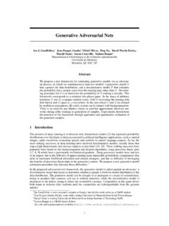
2 6NI ELVISmx Driver 6NI LabVIEW and NI ELVISmx Express VIs .. 6NI myDAQ and NI 7 Getting Started .. aisNI myDAQAUDIO INAnalog InputUSBP ower SupplyGainAnalog OutputDigital Input/OutputAUDIO OUTNI myDAQ System DiagramAIDIO5 V 15 VDC-toDCConverterAnalog-to-DigitalConver terDigital-to-AnalogConverterDigitalMult imeterAnalog ICssupplied byHIHI1 A1 AMAXMAX60 V20 Vrms20 VrmsMAXMAXV V ACOMV ASystem TimingControllerCurrentLimiterAOSwitchMu ltiplexer2| |NI myDAQ user GuideMaking Signal Connections with NI 7 Setting up Your NI myDAQ 7 Connecting Signals .. 9 Connecting Analog Input Signals .. 11NI myDAQ DMM Fuse Replacement .. 13 Digital I/O (DIO) and 16 Using NI myDAQ with NI ELVISmx Software Instruments.
3 16NI ELVISmx Instrument Launcher .. 17 Digital Multimeter (DMM).. 18 Oscilloscope (Scope) .. 19 function generator (FGEN) .. 20 Bode Analyzer ..21 Dynamic Signal Analyzer (DSA) .. 22 arbitrary Waveform Generator (ARB).. 23 Digital Reader .. 24 Digital Writer .. 25 Example: Measuring a Signal Using the NI ELVISmx Oscilloscope with NI myDAQ .. 26 Using NI myDAQ with LabVIEW .. 27NI ELVISmx Express VIs in 27 Example: Measuring Signals Using the NI ELVISmx Oscilloscope Express VI with NI myDAQ .. 28 Using NI-DAQmx with NI myDAQ .. 30 Example: Measuring Audio Pass-Through in LabVIEW with NI myDAQ .. 30 Texas Instruments Components in NI 34 Resource Conflicts.
4 35 Additional Resources .. 37 Related 37 Other Resources ..37 Common Terms and Acronyms .. 38 Warranty .. 39 Worldwide Support and Services .. 39 Safety InformationCautionDo not operate the hardware in a manner not specified in this document and in the user documentation. Misuse of the hardware can result in a hazard. You can compromise the safety protection if the hardware is damaged in any way. If the hardware is damaged, return it to National Instruments for the hardware with a soft, nonmetallic brush. Make sure that the hardware is completely dry and free from contaminants before returning it to myDAQ user GUIDE | National Instruments|3 Electromagnetic Compatibility GuidelinesCautionsTo ensure the specified EMC performance: The USB cable must be less than m ( ft) in length.
5 The length of any wire or cable connected to the 20-pin screw terminal connector must be no longer than m (1 ft). The length of any wire or cable connected to the Audio or DMM ports must be no longer than 3 m (10 ft).This product was tested and complies with the regulatory requirements and limits for electromagnetic compatibility (EMC) as stated in the product specifications. These requirements and limits are designed to provide reasonable protection against harmful interference when the product is operated in its intended operational electromagnetic product is intended for use in residential, commercial, and industrial locations.
6 There is no guarantee that harmful interference will not occur in a particular installation or when the product is connected to a test object. To minimize the potential for the product to cause interference to radio and television reception or to experience unacceptable performance degradation, install and use this product in strict accordance with the instructions in the product , any changes or modifications to the product not expressly approved by National Instruments could void your authority to operate it under your local regulatory myDAQ Hardware OverviewNI myDAQ provides analog input (AI), analog output (AO), digital input and output (DIO), audio, power supplies, and digital multimeter (DMM)
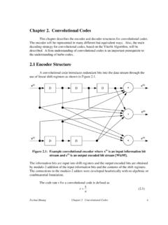
7 functions in a compact USB Common Terms and Acronyms section has a list of acronyms and terms that you will see in this manual, and in many engineering and measurement documents and | |NI myDAQ user GuideIntegrated circuits supplied by Texas Instruments form the power and analog I/O subsystems of NI myDAQ . Figure 2 depicts the arrangement and function of the NI myDAQ subsystems. Refer to Table 5 for more information on all of the Texas Instruments components used in NI 2. NI myDAQ Hardware Block DiagramAnalog Input (AI)There are two analog input channels on NI myDAQ . These channels can be configured either as general-purpose high-impedance differential voltage input or audio input.
8 The analog inputs are multiplexed, meaning a single analog-to-digital converter (ADC) is used to sample both channels. In general-purpose mode, you can measure up to 10 V signals. In audio mode, the two channels represent left and right stereo line level inputs. Analog inputs can be measured at up to 200 kS/s per channel, so they are useful for waveform acquisition. Analog inputs are used in the NI ELVISmx Oscilloscope, Dynamic Signal Analyzer, and Bode Analyzer : NI myDAQ components may be changed or substituted without (CSD25302Q2)DC/DCIsolationTransformer LDOR egulator(TPS76433)LDOR egulator(TPS76433)VBUSI solated + V+15 V+ V+ V+5 V 15 VUSB-STC3 DigitalIsolator(ISO7241)DMMS hiftRegister(SN74 AHC595)Switch(TS5A3159)Regulator(TPS6117 0)IsolationBarrierHIHICOMDAC(DAC8551)Swi tch(TS12A44514)Gain(TLE2082)OP AMP(OPA1642)Audio AMP(TPA6110A2)AO 0AO 1 Line Out RLine Out LInstrumentationAmplifier(OPA1642)Channe lMultiplexerAI 0 AI 0+AI 1 AI 1+Line In LLine In R8 DIO xUSB ConnectorRegulator(TPS62007)Regulator(TP S62003)ADC(ADS8319)OP AMP(OPA1642)CurrentLimiter(TPS2553)(V )(A)
9 + VLDOR egulator(TPS71501)Isolated +5 VNI myDAQ user GUIDE | National Instruments|5 Analog Output (AO)There are two analog output channels on NI myDAQ . These channels can be configured as either general-purpose voltage output or audio output. Both channels have a dedicated digital-to-analog converter (DAC), so they can update simultaneously. In general-purpose mode, you can generate up to 10 V signals. In audio mode, the two channels represent left and right stereo using earphones to listen to the audio output of the NI myDAQ , ensure that the volume is set to a safe level. Listening to audio signals at a high volume may result in permanent hearing myDAQ supports output on either a 10 V or 2 V range and output from either one or both AO channels.
10 When outputting from both AO channels, however, they must share a common voltage a task on an AO channel will set the range for both channels. If a task that was previously running is stopped and a new task is created using the second AO channel set to a different output range, the output on the original channel will scale based on the range of the new outputs can be updated at up to 200 kS/s per channel, making them useful for waveform generation. Analog outputs are used in the NI ELVISmx function generator , arbitrary Waveform Generator, and Bode Analyzer Input/Output (DIO)There are eight DIO lines on NI myDAQ . Each line is a Programmable Function Interface (PFI), meaning that it can be configured as a general-purpose software-timed digital input or output, or it can act as a special function input or output for a digital counter.