Transcription of User Manual English - APCGuard.com
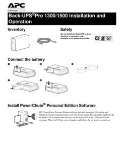
1 990-240406/2005 APC Smart-UPS XL 2200/3000 VA120/230 VACRack Mount 3 UUninterruptible power SupplyUser ManualEnglishSmart-UPS XL 2200/3000 VA 120/230 VAC 3U Rack Mount user Manual3 IntroductionIntroductionAbout this UPSThe APC Uninterruptible power Supply (UPS) provides protection for electronic equipment from utility power blackouts, brownouts, sags and surges. The UPS filters small utility line fluctuations and isolates electronic equipment from large disturbances by internally disconnecting from utility line power . The UPS provides continuous power from the internal battery until utility power returns to safe levels or the battery is fully the Safety Guide before installing the UPS. The user Manual and Safety Guide are accessible on the supplied user Manuals CD and on the APC Web site, the UPS upon receipt.
2 Notify the carrier and dealer if there is packaging is recyclable; save it for reuse or dispose of it the package contents:Specifications UPS Front bezel Rail kit EPO connector UPS literature kit containing: Two mounting brackets Eight flathead screws Product documentation Smart-UPS user Manuals CD PowerChute CD Serial and USB communication cables Safety information Warranty information230V Models Only: UPS literature kit additional contents: Input power cord Alternate input power cord (UK customers) Utility connector plug IEC jumper cablesThe model and serial numbers for all units are located on the rear panel. See the small label with numbers and bar to 104 F (0 to 40 C)5 to 86 F (-15 to 30 C) charge the UPS battery every six months86 to 113 F (30 to 45 C) charge the UPS battery every three monthsThis unit is designed for indoor use only.
3 Select a location sturdy enough to handle the not operate the UPS where there is excessive dust or the temperature or humidity are outside the specified ElevationOperatingStorage10,000 ft (3,000 m)50,000 ft (15,240 m)Humidity0 to 95% relative humidity, non-condensingWeight135 lbs (61 kg) with battery module80 lbs (36 kg) without battery module135 lbs (61 kg)Maximum Number of External Battery Packs Supported by the Smart-UPS XL104 Smart-UPS XL 2200/3000 VA 120/230 VAC 3U Rack Mount user ManualInstallationInstallationYour UPS model may vary from the examples depicted in this UPS and the battery module are heavy. Remove the battery module to lighten the UPS during the Rails in the RackFor details on rail installation refer to the instructions in the rail the UPS in the Rack and Connect the Battery Module4x4x Smart-UPS XL 2200/3000 VA 120/230 VAC 3U Rack Mount user Manual5 Start UpAccessoriesThis UPS is equipped with an accessory SmartSlot.
4 Refer to the APC Web site, for available a standard accessory, such as a SNMP card is installed on this UPS, refer to the Utility CD for user accessories prior to connecting power to the UpConnect Equipment and power to the UPS1. The UPS features a transient voltage surge-suppression (TVSS) screw located on the rear panel, for connecting the ground lead on surge suppression devices such as telephone and network line to connecting the grounding cable, ensure that the UPS is NOT connected to utility or battery Connect equipment to the UPS. NOTE: This UPS is equiped with an external battery connector on the rear panel of the unit. Where appropriate use an APC extension battery cable. For ordering details contact your dealer or APC through the Web site Add optional accessories to the SmartSlot located on the rear Plug the UPS into a two-pole, three-wire, grounded receptacle only.
5 Avoid using extension cords. 230 V models: The utility power cord is supplied in the UPS literature kit. Prior to connecting the utility power , connect the ground lead (optional) to the TVSS V models: Check the SITE WIRING FAULT LED located on the rear panel. The LED will be illuminated if the UPS is plugged into an improperly wired utility power outlet, (see Troubleshooting).6. To use the UPS as a master on/off switch be sure all connected equipment is switched Panels120 VAC 230 VAC6 Smart-UPS XL 2200/3000 VA 120/230 VAC 3U Rack Mount user ManualStart UpStart the UPS1. Press the button on the front panel to start the UPS. The battery charges to 90% capacity during the first four hours of normal operation. Do not expect full battery run capability during this initial charge period.
6 Refer to the APC Web site, for battery For optimal computer system security, install PowerChute Smart-UPS monitoring PortsEmergency power OffThe emergency power off (EPO) feature is user configurable. EPO provides immediate de-energizing of connected equipment from a remote location, without switching to battery Use the EPO connector supplied with the Use a normally-open contact to connect the +24 terminal to the IN terminal. External voltage is not Wire the four-pin connector to the EPO EPO interface is a Safety Extra Low Voltage (SELV) circuit. Connect it only to other SELV circuits. The EPO interface monitors circuits that have no determined voltage potential. Such closure circuits may be provided by a switch or relay properly isolated from the utility.
7 To avoid damage to the UPS, do not connect the EPO interface to any circuit other than a closure type one of the following cable types to connect the UPS to the EPO switch. CL2: Class 2 cable for general use. CL2P: Plenum cable for use in ducts, plenums, and other spaces used for environmental air. CL2R: Riser cable for use in a vertical run in a floor-to-floor shaft. CLEX: Limited use cable for use in dwellings and for use in raceways. For installation in Canada: Use only CSA certified, type ELC, (extra-low voltage control cable). For installation in other countries: Use standard low-voltage cable in accordance with national and local PORTUSB PORTUse only the supplied cable to connect to the serial port. A standard serial interface cable is incompatible with the and USB ports cannot be used PORT (located on rear panel)EPO ConnectorSmart-UPS XL 2200/3000 VA 120/230 VAC 3U Rack Mount user Manual7 OperationOperationDisplay PanelsDisplay Panel Indicators and Function Buttons IndicatorLEDI ndicator TitleDescriptionOn LineThe UPS is supplying utility power to the connected equipment,(see Troubleshooting).
8 AVR TrimThe UPS is compensating for a high utility voltage. Refer to the APC Web site, for AVR BoostThe UPS is compensating for a low utility voltage. Refer to the APC Web site, for AVR BatteryThe UPS is supplying battery power to the connected connected equipment is drawing more than the UPS power rating allows, (see Troubleshooting).Replace Battery/Battery DisconnectedThe battery is disconnected or must be replaced, (see Troubleshooting)./LoadBatteryCharge120 V models230 V models8 Smart-UPS XL 2200/3000 VA 120/230 VAC 3U Rack Mount user ManualOperationDiagnostic Utility VoltageThe UPS has a diagnostic feature that indicates the utility UPS starts a self-test as part of this procedure. The self-test does not affect the voltage and hold the button to view the utility voltage bar graph indicator.
9 After a few seconds, this five-LED Battery Charge indicator on the right of the display panel will show the utility input to the figure on the left for the voltage reading. Values are not listed on the indicator on the UPS shows the voltage is between the displayed value on the list and the next higher value, (see Troubleshooting).Feature ButtonFeature TitleFunctionPower OnPress this button to turn on the UPS. Continue reading for additional OffPress this button to turn off the : The UPS performs a self-test automatically when tuned on, and every two weeks thereafter (by default). During the self-test, the UPS briefly operates the connected equipment on : Press and hold the button for a few seconds to initiate the Start When there is no utility power and the UPS is off, the cold start feature will switch the UPS and connected equipment onto battery power ,(see Troubleshooting).
10 230V120 VBatteryChargeSmart-UPS XL 2200/3000 VA 120/230 VAC 3U Rack Mount user Manual9 ConfigurationConfigurationUPS settingsSettings are adjusted through PowerChute software or optional SmartSlot accessory DefaultUser Selectable ChoicesDescriptionAutomaticSelf-TestOn startup and every 14 days (336 hours) there after Every 7 days(168 hours) On startup and every 14 days (336 hours) there after On startup only No self-testSet the interval at which the UPS will execute a IDUPS_IDENUp to eight characters (alphanumeric)Uniquely identify the UPS, ( server name or location) for network management of LastBatteryReplacementManufacture Datemm/dd/yyReset this date when you replace the battery Capacity Before Return from Shutdown0 percent 0% 15% 30% 45% 60% 75% 90%Specify the percentage to which batteries will be charged following a low battery shutdown before powering connected SensitivityThe UPS detects and reacts to line voltage distortions by transferring to battery operation to protect the connected sensitivityBrightly illuminated: high sensitivityDimly illuminated: medium sensitivityNo illumination: low sensitivityAdjust by pressing the VOLTAGE SENSITIVIY switch (rear panel).