Transcription of Very Low Noise, 24-Bit Analog-to-Digital Converter ...
1 SBAS288K JUNE 2003 REVISED SEPTEMBER 2013 Very Low Noise, 24-BitAnalog-to- digital ConverterADS1255 ADS1256 FEATURESD24 Bits, No Missing Codes All Data Rates and PGA SettingsDUp to 23 Bits Noise-Free ResolutionD Nonlinearity (max)DData Output Rates to 30kSPSDFast Channel Cycling Bits Noise-Free ( Effective Bits)at Conversions with Single-CycleSettlingDFlexible Input Multiplexer with Sensor Detect Four Differential Inputs (ADS1256 only) Eight Single-Ended Inputs (ADS1256 only)DChopper-Stabilized Input BufferDLow-Noise PGA: 27nV Input-Referred NoiseDSelf and System Calibration for All PGAS ettingsD5V Tolerant SPI -Compatible Serial InterfaceDAnalog Supply: 5 VDDigital Supply: to Dissipation As Low as 38mW in Normal Mode in Standby ModeAPPLICATIONSDS cientific InstrumentationDIndustrial Process ControlDMedical EquipmentDTest and MeasurementDWeigh ScalesDESCRIPTIONThe ADS1255 and ADS1256 are extremely low-noise, 24-Bit Analog-to-Digital (A/D) converters.
2 They providecomplete high-resolution measurement solutions for themost demanding Converter is comprised of a 4th-order, delta-sigma( ) modulator followed by a programmable digital filter. Aflexible input multiplexer handles differential orsingle-ended signals and includes circuitry to verify theintegrity of the external sensor connected to the selectable input buffer greatly increases the inputimpedance and the low-noise programmable gainamplifier (PGA) provides gains from 1 to 64 in binary programmable filter allows the user to optimizebetween a resolution of up to 23 bits noise-free and a datarate of up to 30k samples per second (SPS). Theconverters offer fast channel cycling for measuringmultiplexed inputs and can also perform one-shotconversions that settle in just a single is handled over an SPI-compatible serialinterface that can operate with a 2-wire calibration supports both self and systemcorrection of offset and gain errors for all the PGA digital I/Os and a programmable clock outputdriver are provided for general use.
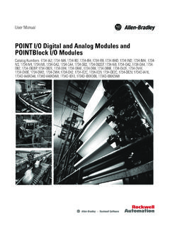
3 The ADS1255 ispackaged in an SSOP-20, and the ADS1256 in is a trademark of Motorola, Inc. All other trademarks are the property of their respective DATA information is current as of publication date. Productsconform to specifications per the terms of Texas Instruments standard processing does not necessarily include testing of all 2003 2013, Texas Instruments IncorporatedPlease be aware that an important notice concerning availability, standard warranty, and use in critical applications of Texas Instrumentssemiconductor products and disclaimers thereto appears at the end of this data Filter4th OrderModulatorVREFPVREFNADS1256 OnlyADS1256 OnlyBufferAVDDDVDD1:64 DGNDD3D2D1D0/CLKOUTAGNDAIN0 AIN1 AIN2 AIN3 AIN4 AIN5 AIN6 AIN7 AINCOMXTAL1/CLKINRESETDRDYSCLKDINSYNC/PD WNCSDOUTC ontrolGeneralPurposeDigital I/OClockGeneratorPGAADS1255 ADS1256 SBAS288K JUNE 2003 REVISED SEPTEMBER INFORMATIONFor the most current package and ordering information, see the Package Option Addendum at the end of this document,or see the TI web site at MAXIMUM RATINGS over operating free-air temperature range unless otherwise noted(1)ADS1255, ADS1256 UNITAVDD to AGND to +6 VDVDD to DGND to + to DGND to + Current100, MomentarymAInput Current10, ContinuousmAAnalog inputs to AGND to AVDD + , SCLK, CS, RESET,SYNC/PDWN,XTAL1/CLKIN to DGND to +6 VinputsD0/CLKOUT, D1, D2, D3to DGND to DVDD + Junction Temperature+150 COperating Temperature Range 40 to +105 CStorage Temperature Range 60 to +150 CLead Temperature (soldering, 10s)+300 C(1)
4 Stresses above those listed under Absolute Maximum Ratingsmay cause permanent damage to the device. Exposure toabsolute maximum conditions for extended periods may degradedevice reliability. These are stress ratings only, and functionaloperation of the device at these or any other conditions beyondthose specified is not integrated circuit can be damaged by ESD. TexasInstruments recommends that all integrated circuits behandled with appropriate precautions. Failure to observeproper handling and installation procedures can cause damage can range from subtle performance degradation tocomplete device failure. Precision integrated circuits may be moresusceptible to damage because very small parametric changes couldcause the device not to meet its published JUNE 2003 REVISED SEPTEMBER CHARACTERISTICS All specifications at 40 C to +85 C, AVDD = +5V, DVDD = + , fCLKIN = , PGA = 1, and VREF = + , unless otherwise CONDITIONSMINTYPMAXUNITA nalog InputsFull-scale input voltage (AINP AINN) 2 VREF/PGAVA bsolute input voltageBuffer offAGND + input voltage(AIN0-7, AINCOM to AGND)Buffer onAGNDAVDD gain amplifier164 Buffer off, PGA = 1, 2, 4, 8, 16150/PGAk Differential input impedanceBuffer off, PGA = 32, ppBuffer on, fDATA 50Hz(1)80M SDCS[1:0] = ASensor detect current sourcesSDCS[1:0] = 102 ASDCS[1.]
5 0] = 1110 ASystem PerformanceResolution24 BitNo missing codesAll data rates and PGA settings24 BitData rate (fDATA)fCLKIN = ,000 SPS(2)Integral nonlinearityDifferential input, PGA = 1 (3)Integral nonlinearityDifferential input, PGA = 64 errorAfter calibrationOn the level of the noiseOffset driftPGA = 1 100nV/ COffset driftPGA = 64 4nV/ CGain errorAfter calibration, PGA = 1, Buffer on errorAfter calibration, PGA = 64, Buffer on driftPGA = 1 CGain driftPGA = 64 CCommon-mode rejectionfCM(4) = 60Hz, fDATA = 30kSPS(5)95110dBNoiseSee Noise Performance TablesAVDD power-supply rejection 5% in AVDD6070dBDVDD power-supply rejection 10% in DVDD100dBVoltage Reference InputsReference input voltage (VREF)VREF VREFP reference input (VREFN)Buffer offAGND reference input (VREFN)Buffer on(6)AGNDVREFP reference input (VREFP)Buffer offVREFN + + reference input (VREFP)Buffer on(6)VREFN + reference impedancefCLKIN = digital Input/OutputVIHDIN, SCLK, XTAL1/CLKIN,SYNC/PDWN, CS, , D1, D2, DVDDVVOHIOH = DVDDVVOLIOL = DVDDVI nput leakage0 < VDIGITAL INPUT < DVDD 10 AMaster clock rateExternal crystal between XTAL1 clock rateExternal oscillator driving JUNE 2003 REVISED SEPTEMBER CHARACTERISTICS (continued)All specifications at 40 C to +85 C, AVDD = +5V, DVDD = + , fCLKIN = , PGA = 1, and VREF = + , unless otherwise mode2 AStandby mode20 AAVDD currentNormal mode, PGA = 1, Buffer off710mAAVDD currentNormal mode, PGA = 64, Buffer off1622mANormal mode, PGA = 1, Buffer on1319mANormal mode, PGA = 64, Buffer on3650mAPower-down mode2 ADVDD currentStandby mode, CLKOUT off,DVDD = ANormal mode, CLKOUT off,DVDD = dissipationNormal mode, PGA = 1, Buffer off,DVDD = dissipationStandby mode, DVDD = RangeSpecified 40+85 COperating 40+105 CStorage 60+150 C(1)
6 See text for more information on input impedance.(2)SPS = samples per second.(3)FSR = full-scale range = 4 VREF/PGA.(4)fCM is the frequency of the common-mode input signal.(5)Placing a notch of the digital filter at 60Hz (setting fDATA = 60 SPS, 30 SPS, 15 SPS, 10 SPS, 5 SPS, or ) will further improve thecommon-mode rejection of this frequency.(6)The reference input range with Buffer on is restricted only if self-calibration or gain self-calibration is to be used. If using system calibration orwriting calibration values directly to the registers, the entire Buffer off range can be JUNE 2003 REVISED SEPTEMBER ASSIGNMENTSSSOP PACKAGE(TOP VIEW)ADS1255 ADS1256 AVDDAGNDVREFNVREFPAINCOMAIN0 AIN1 SYNC, PDWNRESETDVDDD1D0/CLKOUTSCLKDINDOUTDRDYC SXTAL1/CLKINXTAL2 DGNDAVDDAGNDVREFNVREFPAINCOMAIN0 AIN1 SYNC, PDWNRESETDVDDAIN2 AIN3 AIN4 AIN5 AIN6 AIN7D3D1D2D0/CLKOUTDINSCLKDOUTCSDRDYXTAL 1/CLKINDGNDXTAL2123456789101112131415161 7181920987654321101312111420212223242526 27281916171815 Terminal FunctionsTERMINAL power supplyAGND22 AnalogAnalog groundVREFN33 analog inputNegative reference inputVREFP44 analog inputPositive reference inputAINCOM55 analog inputAnalog input commonAIN066 analog inputAnalog input 0 AIN177 analog inputAnalog input 1 AIN2 8 analog inputAnalog input 2 AIN3 9 analog inputAnalog input 3 AIN4 10 analog inputAnalog input 4 AIN5 11 analog inputAnalog input 5 AIN6 12 analog inputAnalog input 6 AIN7 13 analog inputAnalog input 7 SYNC/PDWN814 digital input(1)(2): active lowSynchronization / power down inputRESET915 digital input(1)(2).
7 Active lowReset inputDVDD1016 DigitalDigital power supplyDGND1117 DigitalDigital groundXTAL21218 digital (3)Crystal oscillator connectionXTAL1/CLKIN1319 digital / digital input(2)Crystal oscillator connection / external clock inputCS1420 digital input(1)(2): active lowChip selectDRDY1521 digital output: active lowData ready outputDOUT1622 digital outputSerial data outputDIN1723 digital input(1)(2)Serial data inputSCLK1824 digital input(1)(2)Serial clock inputD0/CLKOUT1925 digital IO(4) digital I/O 0 / clock outputD12026 digital IO(4) digital I/O 1D2 27 digital IO(4) digital I/O 2D3 28 digital IO(4) digital I/O 3(1)Schmitt-Trigger digital input.(2)5V tolerant digital input.(3)Leave disconnected if external clock input is applied to XTAL1/CLKIN.(4)Schmitt-Trigger digital input when the digital I/O is configured as an JUNE 2003 REVISED SEPTEMBER MEASUREMENT INFORMATIONSCLKCSDINDOUTt1t3t2Ht4t5t2Lt6 t9t8t7t11t10 Figure 1.
8 Serial Interface TimingTIMING CHARACTERISTICS FOR FIGURE 1 SYMBOLDESCRIPTIONMINMAXUNITtSCLK period4 CLKIN(1)t1 SCLK period10 DATA(2)tSCLK pulse width: high200nst2 HSCLK pulse width: high9 DATAt2 LSCLK pulse width: low200nst3CS low to first SCLK: setup time(3)0nst4 Valid DIN to SCLK falling edge: setup time50nst5 Valid DIN to SCLK falling edge: hold time50nst6 Delay from last SCLK edge for DIN to first SCLK rising edge for DOUT: RDATA, RDATAC,RREG Commands50 CLKINt7 SCLK rising edge to valid new DOUT: propagation delay(4)50nst8 SCLK rising edge to DOUT invalid: hold time0nst9 Last SCLK falling edge to DOUT high impedanceNOTE: DOUT goes high impedance immediately when CS goes high610 CLKINt10CS low after final SCLK falling edge8 CLKINRREG, WREG, RDATA4 CLKINF inal SCLK falling edge of command to first SCLKRDATAC, SYNC24 CLKINt11 Final SCLK falling edge of command to first SCLK rising edge of next , RESET, STANDBY,SELFOCAL, SYSOCAL, SELFGCAL,SYSGCAL, SELFCALWait for DRDY to go low(1) CLKIN = master clock period = 1/fCLKIN.
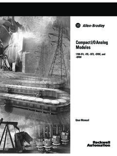
9 (2) DATA = output data period 1/fDATA.(3)CS can be tied low.(4)DOUT load = 20pF 100k to JUNE 2003 REVISED SEPTEMBER 2. SCLK Reset TimingTIMING CHARACTERISTICS FOR FIGURE 2 SYMBOLDESCRIPTIONMINMAXUNITt12 SCLK reset pattern, first high pulse300500 CLKIN(1)t13 SCLK reset pattern, low pulse5 CLKINt14 SCLK reset pattern, second high pulse550750 CLKINt15 SCLK reset pattern, third high pulse10501250 CLKIN(1) CLKIN = master clock period = 1 , SYNC/PDWNCLKINt16 BSYNC/PDWNF igure 3. RESET and SYNC/PDWN TimingTIMING CHARACTERISTICS FOR FIGURE 3 SYMBOLDESCRIPTIONMINMAXUNITt16 RESET, SYNC/PDWN, pulse width4 CLKIN(1)t16 BSYNC/PDWN rising edge to CLKIN rising edge 2525ns(1) CLKIN = master clock period = 1 4. DRDY Update TimingTIMING CHARACTERISTICS FOR FIGURE 4 SYMBOLDESCRIPTIONMINMAXUNITt17 Conversion data invalid while being updated (DRDY shown with no data retrieval)16 CLKIN(1)(1) CLKIN = master clock period = 1 JUNE 2003 REVISED SEPTEMBER CHARACTERISTICSTA = +25 C, AVDD = 5V, DVDD = , fCLKIN = , PGA = 1, and VREF = , unless otherwise DRIFT HISTOGRAMPGA = 190 Units from 3 Production LotsOffset Drift (nV/_C)2520151050 Percent of Population 500 450 400 350 300 250 200 150 100 50050100150200250300350400450500 OFFSET DRIFT HISTOGRAM90 Units from 3 Production LotsOffset Drift (nV/_C)302520151050 Percent of Population 20 18 16 14 12 10 8 6 4 202468101214161820 PGA = 64 GAIN ERROR HISTOGRAM90 Units from 3 Production LotsGain Error (%)302520151050 Percent of Population = 1 GAIN ERROR HISTOGRAM90 Units from 3 Production LotsGain Error (%)
10 2520151050 Percent of Population = 64 GAIN DRIFT HISTOGRAM90 Units from 3 Production LotsGain Drift (ppm/_C)2520151050 Percent of = 1 GAIN DRIFT HISTOGRAM90 Units from 3 Production LotsGain Drift (ppm/_C)2520151050 Percent of = 64 ADS1255 ADS1256 SBAS288K JUNE 2003 REVISED SEPTEMBER CHARACTERISTICS (continued)TA = +25 C, AVDD = 5V, DVDD = , fCLKIN = , PGA = 1, and VREF = , unless otherwise HISTOGRAMPGA = 1 Data Rate = = Off256 ReadingsOutput Code (LSB)100806040200 Percent of Population 5 4 3 2 10 1 2 3 4 5 NOISE HISTOGRAMO utput Code (LSB)2520151050 Percent of Population 20 18 16 14 12 10 8 6 4 202468101214161820 Buffer = Off256 ReadingsPGA = 64 Data Rate = HISTOGRAMO utput Code (LSB)2520151050 Percent of Population 20 18 16 14 12 10 8 6 4 202468101214161820 Buffer = Off4096 ReadingsPGA = 1 Data Rate = 1kSPSNOISE HISTOGRAMO utput Code (LSB)2520151050 Percent of Population 150 135 120 105 90 75 60 45 30 150153045607590105120135150 Buffer = Off4096 ReadingsPGA = 64 Data Rate = 1kSPSNOISE HISTOGRAMO utput Code (LSB)2520151050 Percent of Population 100 90 80 70 60 50 40 30 20 100102030405060708090100 Buffer = Off4096 ReadingsPGA = 1 Data Rate = 30kSPSNOISE HISTOGRAMO utput Code (LSB)2520151050 Percent of Population 600 540 480 420 360 300 240 180 120 60060120180240300360420480540600 Buffer = Off4096 ReadingsPGA = 64 Data Rate = 30kSPSADS1255 ADS1256 SBAS288K JUNE 2003 REVISED SEPTEMBER CHARACTERISTICS (continued)TA = +25 C, AVDD = 5V, DVDD = , fCLKIN = , PGA = 1, and VREF = , unless otherwise NUMBER OF BITSvs INPUT VOLTAGEI nput Voltage, VIN(V) (rms)Data Rate = 1kSPSData Rate = 30kSPSPGA = 1232221201918 EFFECTIVE NUMBER OF BITSvs TEMPERATURET emperature (_C)ENOB (rms) 30 50 101030901107050 Data Rate