Transcription of Vickers Directional Controls - Eaton
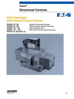
1 Vickers . Directional Controls Mechanical Actuators Directional control Valves Directional control Valves 310 bar (4500 psi). Flows to 114 l/min (30 USgpm). NFPA D05, ISO-4401-05. DG1V4-01**-10 Knob Operated DG17V4-01**-10 Lever Operated Introduction General Description The mechanical Directional control Mechanical operation used by these DG1 and DG17 are manual knob and valves described this brochure are: valves is achieved by hand actuation. lever operated valves used for applications requiring four-way D Knob & Lever operated valves Directional operation. These valves are DG1/17V4-01**-10. offered in spring offset, spring centered and no-spring detented versions. Contents Model Code .. 3. General Information .. 4. Spools, Builds and Operator Variations .. 4. Performance Data .. 5. Fluids and Seals .. 5. Mounting Interface .. 5. Installation Data .. 5. Pressure Drop .. 6. Installation Dimensions .. 7. Suplates & Bolt Kits.
2 9. Application Data .. 11. Typical Sectional View Vickers , Incorporated 1999. All Rights Reserved Model Code Two & Four-way Directional Valves 1 2 3 4 5 6 7 8 9 10 11 12 13 14. 1 Interface seals 6 Valve size 11 Flag symbol Blank - Buna N (std.) 01 - ISO-4401-05, NFPA-D05 interface M - Electrical features (applies only to F3 - VIton (fire resistant seals) switch models). F6 - Nitrile seals (water glycol) Omit if not required 7 Spool type (crossover condition). 0- Open center 12. 2 Directional control Spool indicator switch 1- Open center, B blocked 2- Closed center S3 - Switch wired normally open 3 Mounting type 3- Closed center, P and B blocked S4 - Switch wired normally closed 6- Closed center, P only Omit if not required G- Manifold or subplate 7- Closed center, T blocked 8- Open center, A and B blocked 11 - Open center, A blocked 13 Switch connection 4 control type 22 - Closed center, 2-way U - DIN 43650 connection for switch 17 - Manual lever operated 31 - Closed center, A and P blocked U1 - DIN 43650 connector provided 1 - Knob operated 33 - Closed center, bleed A & B for switch Omit if not required 5 Flow direction 8 Spool/Spring arrangement V4 - Four-way, 310 bar (4500 psi) 14 Design number A- Spring offset (handle out).
3 A2 - Spring offset (handle in) Subject to change. Installation C- Spring centered dimensions remain as shown for design N- No spring detented numbers 10 through 19. 9 Left hand build Omit for standard right hand assembly 10 Handle H- Booted handle for harsh environment Omit if not required Viton is a registered trademark DuPont Co. 3. General Information Spool Variations Build Variations DG**V4-010*-10 DG**V4-018*-10 DG17V4-01*A-10 DG17V4-01*C-10. A B A B. A B A B. P T P T P T P T. DG**V4-011*-10 DG**V4-0111*-10. DG17V4-01*A2-10 DG17V4-01*CL-10. A B A B. A B A B. P T P T. P T P T. DG**V4-012*-10 DG**V4-0122*-10 DG17V4-01*AL-10 DG17V4-01*N-10. A B A B A B A B. P T P T P T P T. DG**V4-013*-10 DG**V4-031*-10 DG17V4-01*A2L-10 DG17V4-01*NL-10. A B A B A B A B. P T P T P T P T. DG**V4-016*-10 DG**V4-033*-10. A B A B. P T P T. DG**V4-017*-10. A B. P T. Operator Variations DG17V4-01**-10 Lever operator DG1V4-01**-10 Knob operator A B A B.
4 P T P T. 4. Performance Data Fluids & Seals Mounting Position Max. pressure P, A & B ports: BUNA-N seals are standard and are No-spring detented valves must be For all spools except type 8 315 bar compatible with water-in-oil emulsions, installed with the longitudinal axis (4500 psi) high water based fluids, and petroleum horizontal for good machine reliability. For type 8 spools only 175 bar oil. F3 (Viton) seals are compatible The mounting position of spring-offset, (2500 psi) with phosphate esters, and F6 seals and spring centered models is Max. pressure T port : 70 bar (1000 psi) are for water glycol. Maximum operating unrestricted. pressure for high water based fluids is 69 bar (1000 psi). Installation Data Max. flow: - All DG17V4 models except type 1 On two-way valves T is the drain Mounting Interface connection and must be piped directly to and 11 spools - 114 l/min (30 USgpm) ISO 4401-05 tank through a surge-free line so there - All DG17V4 models with type 1 CETOP 5 will be no back pressure at this port.
5 And 11 spools - 45 l/min NFPA D05. NOTE. (12 USgpm) Shifting Action Any sliding spool valve, if held for - All DG1V4-01*N models except type Spring offset valves are spring long periods of time, may stick and 1 and 11 spools - 76 l/min positioned unless lever is actuated. not spring return due to fluid residue (20 USgpm). formation and therefore, should be - All DG1V4-01*N models with type Spring centered valves return the spool cycled periodically to prevent this 1 and 11 spools - 45 l/min from happening. to center position when the lever or (12 USgpm). knob control is released. - All DG1V4-01*A/C models - 30 l/min (8 USgpm) No-spring detented valves will remain in the last position attained provided there Handle shift force: is no severe shock, vibration or unusual DG17V4 A 38 N. ( lbs.) pressure transients. DG17V4 C 36 N. ( lbs.). DG17V4 N 20 N. ( lbs.) CAUTION. Operating temperature: Surges of oil in a common tank line 20_ to 50_ C (70_ to 120_ F) serving these and other valves can Weights (approx): be of sufficient magnitude to cause DG1V4: 3,1 kg ( lbs.)
6 Inadvertent shifting of these valves. DG17V4: 3,4 kg ( lbs.) This is particularly critical in the Bolt kits: no-spring detented type valves. (metric) - BK855993M Separate tank lines or a vented (inch) - BDKG01-633 manifold with a continuous SAE grade 8 (metric grade 12,9) or downward path to tank is necessary. better required Max. bolt torque: 12,6 Nm (112 lb. in.). Subplate: 2 kg ( lbs.). Fluid viscosity: 75-250 SUS (15-51 cSt). Fluid Cleanliness - See page 11. 5. Pressure Drop 24 (350) See chart below #4. 21 (300). Pressure Drop bar (psi). 17 (250). #3. 14 (200) #2. 10 (150) #1. 7,0 (100). 3,5 (50). 0 19 (5) 38 (10) 57 (15) 76 (20) 95 (25) 114 (30). Flow l/min (USgpm). Pressure Drop Reference Curve Model Code P-A P-B A-T B-T P-T. DG17V4-010*-10 1 1 1 2 2. DG17V4-011*-10 1 1 1 2 2. DG17V4-012*-10 2 2 1 2 - DG17V4-013*-10 2 2 1 2 - DG17V4-016*-10 2 2 1 2 - DG17V4-017*-10 1 1 3 3 - DG17V4-018*-10 4 4 3 4 2. DG17V4-0111*-10 1 1 2 2 2.
7 DG17V4-0122*-10 2 2 - - - DG17V4-0131*-10 2 2 1 2 - DG17V4-0133*-10 2 2 1 3 - 1. Figures in the pressure drop chart Viscosity give approximate pressure drops cSt 14 20 43 54 65 76 85. ( P) when passing 20,5 cSt (100 SUS) fluid having .865 specific (SUS) (17,5) (97,8) (200) (250) (300) (350) (400). gravity. % of P. (Approx.) 81 88 104 111 116 120 124. 2. For any other flow rate (Q1), the pressure drop ( P1) will be 4. For any other specific gravity (G1)*, approximately: the pressure drop ( P1), will be P1 = P(Q1/Q2)2 approximately: P1 = P(G1/G). 3. For any other viscosity(s), the * Specific gravity of fluid may be obtained from its producer. pressure drop ( P) will change as The value is higher for fire-resistant fluids than for oil. follows: 6. Installation Dimensions Manual Lever Operated Valves Millimeters (inches). 18_. DG17V4-01*A-10 88,1 ( ). DG1(7)V4-01*A-(H)-M-S*-U(1)-10. DG17V4-01*A2-10. Position #3 (extreme in) U1 - DIN 43650 connector Neutral for supplied for switch connection DG17V4-01*A2-10 models Position #1 (extreme out) U - DIN 43650.
8 Neutral for for switch DG17V4-01*A-10 models 22,7. (.90). 49,9. ( ). 179,4. ( ). 33,1. ( ). 61,2. 79,3 ( ). ( ). 175,3. ( ). Manual Knob Operated Valve DG1V4-01**-10. Position #3 47,3 ( ). Position #2. Position #1. 3,6. (.14). 3,6 (.14) stroke stroke 7. Spring Centered & No-Spring Detented Manual Lever Operated Valves Millimeters (inches) 41,1.. DG17V4-01-*C-10 ( ). Position #3 - extreme in DG17V4-01-*N-10. Position #2 - intermediate Position #1 - extreme out 44,0 44,0. ( ) ( ). 176,3. ( ). 179,4 4,8. ( ) (.19). 57,1. ( ) 22,2 28,4 36. (.88) 98,4 ( ) ( ). NFPA D-01 (ISO 4401-05, CETOP 5). interface, seals included ( ). 175,3. ( ). Mechanically Operated 14_ 14_. for Harsh Environments millimeters (inches) 39,2 ( ) 39,2 ( ). DG17V4-01**-H-10. 162,9. ( ). 34,9 ( ). 51,1 173,1. ( ) ( ). 8. Subplates & Bolt Kits Valves, subplates and mounting bolts must be ordered separately. Example: One (1) DG17V4-012A-10 Valve One (1) DGSM(E)-01-20-T8 Subplate One (1) BKDG01-633 Bolt Kit When subplate is not used, a machined pad must be provided for mounting.
9 Pad must be flat within 0,0127 mm (.0005 inch). and smooth within 63 microinch. Mounting bolts, when provided by customer, should be SAE grade 7 or better. Torque mounting bolts to: 13 Nm (115 lb. in.). Mounting Subplate DGSM-01-20-T8. Millimeters (inches) P Pressure Conn. 10,3 (.41 D.) Thru 20,6 (.81 D.). 50,8. ( ) Spotface 4-holes for mounting 39,6. ( )..438 Dia. System ports 28,5. 4 holes ( ). 10,4 (.41) 5,6. B Cyl. Conn. (.22). 10,4 (.41). 6,35 15,8 5,6. (.25) 23,9 (.94) (.62) (.22). 15 114,3. (.59) ( ). 92. ( ) P. 26,16. 46 43,7 B T. ( ). ( ) ( ). A. 23,1. 12,7 (.91) 101,6. (.50) ( ). 79,4 54 23,9 20,6. 33,02 ( ) ( ) (.94) (.81). ( ). 31,8 .750-16 UNF-2B Thd. 4 holes A Cyl. Conn. T Tank Conn. 1/ thd. ( ) System connections. User to 4 plug port B of subplate used with DG16 valve..250-20 UNC-2B Thd. 4-holes for mounting 9. Mounting Subplate DGSME-01-20-T8. Millimeters (inches) P Pressure Conn. 1/ thd. 2. 10,3 (.)
10 41 D.) Thru 20,6 (.81 D.). 50,8. ( ) Spotface 4-holes for mounting 39,6. ( )..438 Dia. System ports 4 holes 10,4 (.41). B Cyl. Conn. 10,4 (.41) 1/ thd. 6,35 2. (.25) 23,9 (.94). P. 15. (.59). 92. ( ). 26,16 114,3. ( ) 46 B. ( ) ( ). T. 23,1. 12,7 (.91) A. (.50) 101,6. 79,4 54 23,9 ( ). 33,02 ( ) ( ) (.94). ( ). A Cyl. Conn. 39,1. T Tank Conn. 1/ thd. ( ). 1/ thd. 2. 2..250-20 UNC-2B Thd. 4-holes for mounting 10. Application Data Fluid Cleanliness Recommendations on filtration and the Vickers products, as any components, Proper fluid condition is essential for selection of products to control fluid will operate with apparent satisfaction in long and satisfactory life of hydraulic condition are included in 561. fluids with higher cleanliness codes than components and systems. Hydraulic those described. Other manufacturers fluid must have the correct balance of Recommended cleanliness levels, using will often recommend levels above cleanliness, and additives for protection petroleum oil under common conditions, those specified.