Transcription of Vickers Directional Controls Solenoid Operated Directional ...
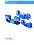
1 5049/EN/0596/ARevised 06/96DG4V-3S, EN 490 For Mobile EquipmentFlows to 40 l/min ( USgpm), 6* DesignP, A & B Pressures to 350 bar (5000 psi), T Pressures to 210 bar (3000 psi)General DescriptionThis Solenoid Operated directionalcontrol valve is for directing andstopping flow at any point in a hydraulicsystem. Its primary function is todetermine the direction of fluid flow in awork cylinder or control the direction ofrotation of a fluid connections are made by mountingthe valve on a subplate or manifold. Thevalve has wet armature type is derived from the standard modelseries is distinguished as a special by theEN490 designation.
2 Electricalconnections to the valve are typicallymade directly to the Solenoid by variousplug-in devices. Solenoids are availablein DC voltages and Benefits Special design for high tank linerating. Tank line can withstandpressures up to 210 bar (3000 psi).Ideal replacement for DG4V-3 for hightank line pressure applications. Meets key OEM specificationsregarding temperature, vibration, heatrise/drop, impact test, water dunk(thermal shock and hermetic seal),salt spray and dielectric strength test. High thermal shock and impactresistance due to new coil around coil ensures highstrength and allows frame toexpand/contract without added stress.
3 Available with molded-in surgesuppressor/diodes to protect PLCs orcircuit boards from backelectro-magnetic force (EMF). Variety of manual override options areavailable: plain, water-resistant andlatching. High performance features includingminimal pressure drop, scratch-proofoverride seals, high reliability, multipleelectrical connections and ease Operating Pressure A , B and P ports: 350 Bar (5000 psi)Maximum Tank Line Pressure210 bar (3000 psi)Mounting InterfaceISO 4401-AB-03-4-ACETOP 3 or NFPA D03 (formerly D01) ANSI (approximate)Single Solenoid models:1,6 kg ( lb)Double Solenoid models.
4 2,2 kg ( lb)ReferenceGB-C-2015 Solenoid OperatedDirectional ValvesVickers Directional ControlsSolenoid Operated Directional Valve Vickers , Incorporated 1996 All Rights ReservedContentsModel Code3.. Performance Data4.. Installation Dimensions6.. Electrical Plugs & Connectors7.. Mounting Bolts10.. Mounting Interface11.. 3 Model Code34587691012111213141512 Directional control ValveDG4V - Subplate mounting; solenoidoperated. Pressure rating 350 bar(5000 psi) for ports P, A & Valve3S - Standard performance; up to 40l/min ( USgpm) at 350 bar (5000 psi)Spool Type0 -Open center (all ports)2 -Closed center (all ports)6 -Closed center (P blocked) A & B to T7 -Open center (P to A & B) T blocked8 -Tandem center (P to T) open crossover22 - Closed center (two way)33 - Closed center, bleed A & B to T34 - Closed center, bleed A & B to T52 - Closed center (all ports) regen.
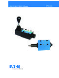
5 Towards workport A56 - A&B to T, P blocked, regen. by Solenoid A66 - Closed center (P blocked) A & B to T521 - Closed center (all ports) regen. towards workport B561 - A&B to T, P blocked, regen. by Solenoid BSpool/Spring ArrangementA - Spring offset, end-to-endAL - Same as A but left hand buildB - Spring offset, end to centerBL - Same as B but left hand buildC - Spring centeredF -Spring offset, shift to centerFL - Same as F but left hand build345678911101213 Manual Override OptionsNo symbol - Plain override(s) insolenoid end(s) only H - Water-resistant override(s) on Solenoid end(s) H2 - Water resistant overrides on both endsP2 - Standard overrides on both endsY -Latching manual override(s)
6 On Solenoid end(s) (includes H feature seal) No override in non- Solenoid end of single Solenoid Energization IdentityV - Solenoid A is at port A end/or Solenoid B is at port B end, independent of spool for ANSI standardrequiring Solenoid A energization toconnect P to A and/or Solenoid B toconnect P to B, independent of SymbolM - Electrical options and featuresCoil TypeU - ISO 4400 (DIN 43650) mounting U1 - ISO 4400 (DIN 43650) mounting, with connectorU6 - ISO 4400 (DIN 43650) mounting, with connector and lightsKU - Top exit flying leadsSP1- Single ( in) spade connector to IEC 760 (NFPA, SAE J858a, Type 1A) (Internal ground)SP2- Dual ( in) spade connector to IEC 760 (NFPA, SAE J858a, Type 1A) Female connector to be supplied by Exit Connectors (KU type only)Omit for no - Packard Weatherpak Connector (female)P6 - Deutsch Connector (male)P7 - Packard Weatherpak Pins (male)P12- Packard Weatherpak Connector (male)Surge Suppressor/DamperOmit for not - Encapsulated diode ve to right.
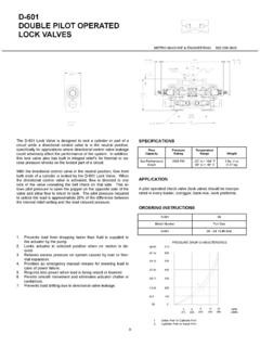
7 +ve to left when facing retaining nutCoil RatingG - 12 VDCH - 24 VDCPort T Rating7 -210 bar (3000 psi)Design NumberSubject to change, installationdimensions remain as shown for designnumbers 60 through VersionStandard performance version with 210bar (3000 psi) tank rating. Solenoid withexternal frame for improved thermalstability, improved hermetic Restrictor PlugsOmit if no restrictor plugs are details of plug orifice sizes and howto specify in model code, see page l/min0246810 USgpmFlow ratepsibar500040003000200010000050100150 200250300350 Pressure12345678 Spool/SpringCurve Code0A(L)30B(L) & 0C, 0F12A(L)32B(L) & 2C, 2F36B(L) & 6C, 6F57B(L) & 7C, 7F28B(L) & 8C8 22A(L)722B(L) & 22C633B(L) & 33C434B(L) & 34C552BL, 52C,5 56BL & 56C566B(L)
8 & 66C5521B & 561B5 Consult Vickers regarding eachapplication that will jointly haveflow rates approaching this curveand a pressurized volumeexceeding 2000 cm3 (122 ).4 Performance DataFeaturePressure limits:P, A and B portsT port350 bar (5000 psi) 210 bar (3000 psi)Flow ratingSee performance dataRelative duty factorContinuous; ED = 100%Type of protection:ISO 4400 coils with plug fitted correctlySP1 Single spade 6,3 mmSP2 Dual spade 6,3 mmCoil windingLead wires (coils type KU)Coil encapsulationIEC 144 class IP67 (depending on connector)IEC 760 IEC 760 Class HClass HClass FPermissable voltage fluctuation:MaximumMinimumRefer to temperature ratedTypical response times at 100% rated volts measured fromapplication/removal of voltage to full spool displacement of 2C spool at.
9 Flow rate P-A, B-TPressureDC (=) energizingDC (=) de energizing20 l/min ( USgpm)175 bar (2537 psi)60 ms40 msPower ConsumptionDC solenoids at rated voltage and 20 C (68 F).Full power coils:12V, model type G 24V, model type H 30W30 WMaximum flow ratesPerformance based on full powersolenoid coils warm and operating at90% rated with mineral oil at 36 cSt( SUS) and a specific gravity of other viscosities, pressure dropsapproximate to:Viscosity cSt (SUS) 14 20 43 54 65 76 85( ) ( ) (200) (251) (302) (352) (399)% of p 81 88 104 111 116 120 124A change to another specific gravitywill yield an approximately proportionalchange in pressure specific gravity of a fluid may beobtained from its producer.
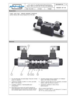
10 Fireresistant fluids usually have higherspecific gravities than 69160140120100806040200 Pressure dropFlow ratel/minUSgpmpsibar12111098765432110203 00l/min0 2468 USgpm14012010080604020151413psibar200016 0012008004000 Flow ratePressure drop5 Pressure dropsPressure drops in offset positions except where otherwise indicatedSpool/springcodeSpoolpositionsc overedP to AP to BA to TB to TP to TB to AorA to B0A(L)Both5522 0B(L) & 0C, 0 FDe-energizedEnergized 4 4 2 24 n 2A(L)Both6655 2B(L) & 2C, 2 FEnergized5522 6B(L) & 6C, 6 FDe-energizedEnergized 6 63 13n1 7B(L) & 7C, 7 FDe-energizedEnergized6 46n4 3 3 7 8B(L) & 8 CAll99553 22A(L), 22B(L)& 22 CAll66 33B(L) & 33 CDe-energizedEnergized 5 515 215n2 34B(L) & 34 CDe-energizedEnergized 5 514 214n2 52BL & 52 CEnergized6 6n2 10 56 BLBoth6 6n11 10n 10 56 CDe-energizedEnergized 6 6n11 210n 10 10 66B(L)