Transcription of VICKERS Overhaul Manual Directional Control Valves
1 Solenoid Pilot OperatedOverhaul ManualVICKERS Directional Control Valves2 ContentsSection I. Introduction3.. Model Code Breakdown4.. Section II. Description6.. Section III. Valve Operation7.. Section IV. Pilot Valve Section13.. Section V. Internal Valve Functions15.. Section VI. Installation16.. Section VII. Service, Inspection & Maintenance18.. Section VIII. Overhaul19.. DG5V-8-S/H-*(C)-1025.. DG3V-8-*(D) (2/8 / 28)-1026.. DG4V-3(S)-*A(L)/B(L)-FJ/FW-6027.. DG4S4-01*B/C-(U)-*-6028.. Section IX. Start-Up and Test28.. 3 Section I. - Introduction A. Purpose of ManualThis Manual describes operational characteristics,maintenance requirements, and Overhaul information forVickers DG3V-10 and DG5V-10 series single stage and twostage pilot operated and hydraulic operated directionalvalves. The information contained herein pertains to thelatest design series as listed in Table Related PublicationsService parts and installation dimensions are not containedin this Manual .
2 The parts and installation drawings listed inTable 1 are available from any VICKERS DistributorC. Model CodesVariations within each basic model series are covered in themodel code. See Table 2. Each unit has a model codestamped into the main stage nameplate. Service inquiriesshould always include the complete model number as notedon the DescriptionApplication DrawingParts DrawingDG3V-10*ADG3V-10* *DDG5V-10*ADG5V-10*B5007 01/EN/0196/ADG5V-10* * *DADG5V-10*DBDG5V-10*NTable 1. Related Publications4 Model Code Breakdown Model Code2376819 Special Seals(Omit if not required)F3 - Seals for fire resistant - Seals for water Control ValveDG3V - Subplate mounting; pilot operated, remote operator. Pressurerating 350 bar (5000 psi) for P, A & Bports. (See pressure tabulation below.)Valve Size10 - Valve size CETOP 10, ISO 4401-10,NFPA D10 Gauge PortsBlank - .4375-20 UNF-2B ThreadB -1/4 BSP ThreadSpool Types0 -Open to T all ports1 -Open P&A to T, closed B2 -Closed to T all ports3 -Closed P&B, open A to T4 -Tandem P to T, closed crossover6 -Closed P only, open A&B to T7 -Open P to A&B, closed T8 -Tandem P to T, open crossover9 -Open to T all ports over tapers11 - Open P&B to T, closed A31 - Closed P&A, open B to T133 - Closed P, open A&B to T over tapers52 - Closed center, regen.
3 By sol. A 521 - Closed center, regen. by sol. B Spool/Spring ArrangementBlank - No springA - Spring offset to cylinder A C - Spring centeredD - Pressure centered 140-210 bar (2000 - 3000 psi)(See spool/spring combinations below)Left Hand BuildL - A Models only, omit if not ResponseX- Not available with CETOP 3 pilots orpressure centered D and DB Control Modifications(Omit if not required)1 -Stroke adjustment (both ends) available on C & Blank(no spring) models)2 -Pilot choke adjustment(available on all models)3 -Pilot choke and stroke adjusters (both ends) (available on C & Blank(no spring) models)2346797 -Stroke adjusters on cylinder A endonly (available on AL, C & Blank (no spring) models)8 -Stroke adjusters on cylinder B endonly (available on AL, C, & Blank (no spring) models)2-7 - If both are required (available on A,C, & Blank (no spring) models)2-8If both are required (available on AL left hand build, C & Blank (no spring) models)Check Valve in Pressure PortNot available for D modelsOmit if not - 0,3 bar (5 psi) checkQ - 2,4 bar (35 psi) checkR - 3,4 bar (50 psi) checkS - 5,2 bar (75 psi) checkDesign NumberSubject to change.
4 Installationdimensions remain as shown for designnumbers 10 through Modifications(Omit if not required)EN503- Reduced overall axial length for close quarter Seals(Omit if not required)F3 - Seals for fire resistant - Seals for water Control ValveDG5V - Subplate mounting; solenoidcontrolled; pilot operated. Pressurerating 350 bar (5000 psi) for P, A, & : 210 bar (3000 psi) for pressurecentered D Size10 - Valve size CETOP 10, ISO 4401-10,NFPA D10 Pilot Valve TypeH - CETOP 3 mounting pattern, High performanceS - CETOP 3 mounting pattern, Std. performanceA - CETOP 5 mounting pattern, Air gapF - CETOP 5 mounting pattern, Wet armatureV - CETOP 5 mounting pattern, Wet armatureW -CETOP 5 mounting pattern, Wet armature(See page NO TAG for descriptions)Reducer Module(Omit if not required)R - A (air gap) and W (wet armature)piloted models when pilot pressureexceeds 210 bar (3000 psi); F and V(wet armature) when pilot pressureexceeds 310 bar (4500 psi).
5 Gauge PortsBlank - .4375-20 UNF-2B ThreadB -1/4 BSP ThreadM -ISO 6149 portSpool Types0 -Open to T all ports1 -Open P&A to T, closed B2 -Closed to T all portsFast ResponseX - (Omit for standard internal pilot pressure models)NoteNot available for pilot pressures above210 bar (3000 psi), pressure centeredmodels must have DA 20-70 bar(300-1000 psi) in model code. Notavailable for H or S piloted Control Modifications(Omit if not required)1 - Stroke adjustment (both ends) (available on B, C, & N models)2 - Pilot choke adjustment (available on all models)3 - Pilot choke and stroke adjustments (both ends) (available on B, C, & N models)7 - Stroke adjustment on cylinder A end only (available on A, B, C, & N models)8 - Stroke adjustment on cylinder B end only (available on AL, B, C, N, & D(*) models)2-7 - If both are required (available on A, B, C, & N models)2-8 - If both are required (available on AL, B, C, N, & D(*) models)CAUTIONS troke adjust pilot pressuremodels are rated to amaximum of 210 bar (3000psi).
6 Use reducer module if pilotpressure exceeds 210 bar (3000 psi).External Pilot PressureE -External pilot pressure. Omit for internal pilot pressure Pilot DrainT - Internal pilot drain to T port. Omit for external pilot drain Valve in Pressure PortNot available for D(*) if not - 0,3 bar (5 psi) checkQ - 2,5 bar (35 psi) checkR - 3,5 bar (50 psi) checkS - 5, bar (75 psi) check123458763 -Closed P&B, open A to T4 -Tandem P to T, closed crossover6 -Closed P only, open A&B to T7 -Open P to A&B, closed T8 -Tandem P to T, open crossover9 -Open to T all ports over tapers11 - Open P&B to T, closed A31 - Closed P&A, open B to T33 - Closed P, open A&B to T over tapers52 - Closed center, regen. by sol. A 56 - A&B to T, P blocked, regen. by sol. A 521 - Closed center, regen. by sol. B 561 - A&B to T, P blocked, sol. B Spool/Spring ArrangementA - Spring offsetB - Spring centered with solenoid A removedC - Spring centeredD - Pressure centered 210-350 bar (2000-3000 psi)DA - Pressure centered 20-70 bar (300-1000 psi)DB - Pressure centered 70-210 bar (1000-2000 psi)N - DetentedLeft Hand BuildL - Single solenoid models only, omit if not Override OptionsCETOP 3 piloted models only, omit if - Plain override in solenoid ends - Waterproof override in solenoid ends only.
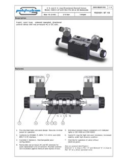
7 H2- Waterproof override in both ends of single Plain override in both ends of single Lockable Manual override in solenoid ends No override in either Code6 Section II. - Description A. GeneralDirectional Valves are devices used to change the flowdirection of fluid within a hydraulic circuit. A valve isdesigned to Control the direction of movement of a workcylinder or the direction of rotation of a fluid Basic Four-Way Sliding Spool Directional ValveConstructionVickers valve bodies have a precision machined bore inwhich a very close tolerance spool is suspended on a film ofhydraulic fluid. Spool lands and body cavities are designedto divide the bore openings into separate chambers. Ports inthe body lead into these chambers so that spool positiondetermines which ports are open or closed. See Figure 1. Oilflow is directed from one port to another within the body andout of a port to the workC.
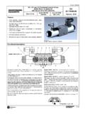
8 Two Stage Directional Valve ConstructionTwo stage Directional Valves are pilot pressure operated. Atwo stage valve is constructed by combining a pilot valveand a larger main stage valve into one assembly. The pilotvalve, usually a DG4S4 or DG4V-3 is mounted on top of themain stage valve. The pilot valve controls spool movementwith the elecrical solenoids. When a solenoid is energized(activated), the pilot spool moves and fluid is diverted to themainstage; thus controlling main stage spool 2 illustrates the basic construction of a two stage,pilot operated Directional 1. Spool Type Four-Way ValveFigure 2. Typical DG5 Type Solenoid Controlled, Pilot Operated Valve7 Section III. - Valve Operation A. GeneralDirectional valve operation is determined by four factors:spool type, spool positioning, method of Control , and specialfeatures. Proper selection of the above factors establish andregulate desired flow paths through the internal ports of thevalve.
9 The following information discusses those factors withrespect to valve Spool Types - Main Stage SectionOperation of spools are governed by their design as well asthe means of Control . The most common designs are opencenter, closed center and tandem. During the followingdiscussion, basic spool design is related to valve portopenings, with the spool in center position. Port openingsare stated as: P-Pressure Port, A&B-Actuator Ports, andT-Tank or Reservoir Open Center Spools (0, 1, 9 and 11 types): Open centervalves are used in single operations where no otheroperation is performed by the same source of power andwhere cylinders do not have to be held by pressure. Opencenter spools are also used to minimize shock in a develops when a valve spool is shifted from oneposition to another across center position. The smoothestpossible minimum shock condition is obtained when fluidunder pressure is allowed to discharge to tank as the spoolpasses center center with (A) or (B) ports blocked.
10 A spool of thistype is generally used to operate a cylinder. When the spoolis centered, a cylinder port is blocked and the cylinder is heldin a definite position. In some circuits, flow from the tank portis piped into the pressure port of another valve. This allowsthe same source of power to operate two different type of arrangement may be used in a systemcontaining a number of operations. However, each operationmust be performed in a certain sequence, with only oneoperation taking place at any one Type 0 spool is designed with ports (P), (B), (A) and(T) interconnected when the spool is in ports are momentarily interconnectedduring spool crossover when the pilot valve solenoid isactivated. This permits smooth rapid cycle CenterB. Type 1 spool is designed with ports (P), (A) and (T)interconnected. Port (B) is blocked in center B Closed - Pressure Opento Tank through A TAPBC.