Transcription of Vickers Pressure Relief Pressure Relief Valves for …
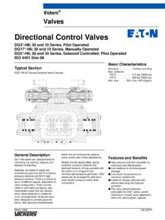
1 May 1996GB-2330 AECT-06/10, 10 Series; ECT5-06/10, 30 SeriesTypical SectionECT5-10 exampleBasic CharacteristicsMax. pressure250 bar (3625 psi).. Max. flow rates:ECT(5)-06200 L/min (757 US gpm).. ECT(5)-10380 L/min (1440 US gpm).. General DescriptionThese adjustable Pressure Relief valveslimit system Pressure by directing pumpflow to reservoir when the systempressure reaches the setting of thevalve, thus preventing overloading thesystem. Their two-stage design ensuresfast response and minimal pressureoverride. In addition to the conventionalrelief valve operation, a pilot ventingfeature allows the system Pressure to bedropped to near-zero, or to a valve is available in two versions:type ECT5, with integral solenoidoperated pilot valve, and in basic form,type the ECT5 version, the pilot valveprovides for selection of up to threepressures or one/two pressures plusoff-loading according to the model circuitry options can be furtherextended by the use of remote both the ECT and ECT5 versionsthe Vent port can be connected to anon/off valve for load/unload, or to apressure pilot valve for remote control ofthe Pressure both models the integral manualpressure adjustment is available asscrew/locknut, or micrometer Pressure ReliefPressure Relief Valves for Pipe MountingFunctional SymbolsECT5-**(V)-0C Both solenoids de-energized = VentedRight-hand solenoid energized =On-load, externally controlled at ALeft-hand solenoid energized =On-load, externally controlled at BECT5-**(V)
2 -2 CBoth solenoids de-energized = On-load,by integral controlRight-hand solenoid energized =On-load, externally controlled at ALeft-hand solenoid energized =On-load, externally controlled at BECT5-**(V)-0B Solenoid de-energized = VentedSolenoid energized = On-load, byintegral controlECT5-**(V)-2A Solenoid de-energized = On-load,externally controlled at A (or integralcontrol if A plugged)Solenoid energized = On-load,externally controlled at B (or integralcontrol if B plugged)ECT5-**(V)-0 BLSolenoid de-energized = VentedSolenoid energized = On-load, byintegral controlECT5-**(V)-2AL Solenoid de-energized = On-load,externally controlled at B (or integralcontrol if B plugged)Solenoid energized = On-load,externally controlled at A (or integralcontrol if A plugged)PPTVentNotes:1. All Valves : Vent port fitted with removable ECT5 models: A and B ports fitted with removable ECT5 models: Each valve carries two nameplates:The mainstage valve carries the lower half of the functional symbol and shows the full valve model solenoid pilot valve carries the upper part of the functional symbol and shows the model code of the individual pilot solenoid identities, Sol.
3 A / Sol. B , see nine pages on. PPTVentABPTY PPTVentABPTX PPTVentABPTX Y PPTVentABPTY PPTVentABPTX PPTVentABPTX Y 2 ECT valvesModel CodesBasic Models (Without Integral Solenoid Pilot Valve)(F3-)Fluid compatibilityBlank = Anti-wear hydraulic oil (class L-HM), invert emulsion (class L-HFB) or water glycol (class L-HFC)F3 = As above or phosphate ester (class L-HFD)Nominal bore size06 =3/4 10 = 11/4 Pressure adjustment rangeB = 5 to 70 bar (75 to 1000 psi)C = 35 to 140 bar (500 to 2000 psi)F = 100 to 250 bar (1450 to 3625 psi)High vent springOmit for low vent springPressure adjustment methodK = Micrometer with keylockOmit for screw/locknut methodIntegral pilot valve spool/spring arrangement0B0BL0C2A2AL2 CManual override optionsOverride option in solenoid end(s) onlyBlank = Plain manual override H = Water-resistant override on DC solenoids onlyZ = No overrideECT-TB* (V)(-K) 1*14312 Solenoid identity methodV = Solenoid A at port A end of pilot valve.
4 Solenoid B at B end of pilot valve (German practice).Omit for solenoid identity to USA standard, energize solenoid A for P to A; solenoid B for P to connection type U= ISO 4400 (DIN 43650) on coil FW =1/2 NPT thread conduit boxFTW=1/2 NPT thread conduit box andterminal stripFJ = M20 thread conduit boxFTJ = M20 thread conduit box and terminal strip Other connection types as shown in catalog 2015 (DG4V-3/3S) may be made available depending on quantities. Female connector to be supplied by lightsOption for solenoid connection typesF(T)W and F(T)J L = Lights fittedOmit if lights not U type coil use plug with integral light, see ninepages ratingA= 110V ACB = 110V AC 50 Hz/120V AC 60 HzC= 220V AC 50 HzD = 220V AC 50 Hz/240V AC 60 HzG= 12V DCH= 24V DC For 60 Hz or dual number10 series for ECT models30 series for ECT5 models Subject to change. Installationdimensions unaltered for designnumbers 10-19 and 30-39 **2-5 Models With Integral Solenoid Pilot Valve(F3-)ECT5-TB(-*) (V) M-3*16**9* (V)(-K)43**2-57-** (L)-810*115-12789101112 See Functional Symbols 3 Features in brackets ( ) may be omitted if not required.
5 All other features must be Data4 Typical with petroleum oil at 21 cSt (102 SUS) and at 50 C (122 F).Maximum pressures:Ports P, A, B and VentPort T :ECT, 10 seriesECT5, 30 series Normally this is connected directly to the reservoir. Back Pressure at port T is additive to the valve setting: if the back Pressure exceeds system Pressure by approx. 7 bar (100 psi), reverse flow T to P may bar (3625 psi)250 bar (3625 psi)100 bar (1450 psi)ECT5, 30 series Valves are designed to satisfy the needs of mostapplications. Consult your Vickers representative about analternative model if:a) Valves are required to remain pressurized for long periodswithout frequent switching, and/orb) Back Pressure at port T is required to rise above 100 bar(1450 psi). Pressure adjustment rangesSee Model Code 3 Maximum flow rates:ECT(5)-06 ECT(5)-10200 L/min (757 US gpm)380 L/min (1440 US gpm) Pressure overrideSee next pageVent pressuresSee next pageVent flowSee next pageResponse times, ECT5 modelsSee two pages onTank port leakage with valve set at max.
6 Pressure ; Pressure at port P = 50% of max. (5)-**BECT(5)-**CECT(5)-**F<200 cm3/min ( in3/min)<300 cm3/min ( in3/min)<500 cm3/min ( in3/min)Thermal stabilitySee two pages onElectrical Data for ECT5 ModelsCoil voltagesSee Model Code 11 Permissible voltage fluctuation:MaximumMinimumSee Temperature Limits , three pages on90% of rated voltage, see Model Code 11 Relative duty factorContinuous, ED = 100%Types of protection:ISO 4400 coils with plug fitted correctlyConduit boxCoil windingLead wires (coils type F**)Coil encapsulationIEC144, class IP65 IEC144, class IP65 Class HClass HClass FPower consumption for coils listed in Model Code :AC coils:Types A, C at 50 HzTypes B, D at 50 HzTypes B, D at 60 HzDC coils:GH11 Initial HoldingVA VA (rms)(rms)22539265492604830W 30W 1st half cycle; solenoid armature fully retractedPerformance Characteristics3002001000barpsi400030002 0001000010020050150250L/min0102030405060 70 US gpmFlow ratePressureECT(5)-06 models3002001000barpsi400030002000100001 00200L/min0204060US gpmFlow ratePressureECT(5)-10 models300400801000barpsi010020050150250L /min0 102030 40506070 US gpmFlow ratePressureECT(5)-06 modelsVent Pressure Levels2468255075100 High vent spring V Low ventspringbarpsi0L/minUS gpmPressureECT(5)-10 models246825507510001002000204060 Flow rate30040080100 High vent spring V Low ventspring0L/minUS gpmValid for ECT(5)-06 and -10 models20100200020406030040080100 High vent spring V Low ventspring13L/minUS main flow rateVented pilot flow rateVent Flow/Main Flow5 Typical with petroleum oil at 21 cSt (102 SUS) and at 50 C (122 F)unless stated Override at various settings3002001000barpsi4000300020001000 0203040506070 Pressure C FTemperature80100120140160203040506070 ECT(5)
7 -**V high vent Pressure models C FTemperature80100120140160123456 gpmFlow ratebar (psi)250 (3600)203040506070 Under remote control conditions, vent line flow through pilotrelief valve set at various pressures; main Valves at maximumflow rates C FTemperature80100120140160123456 gpmFlow ratebar (psi)250 (3600)ECT(5)-** low vent Pressure models207 (3000)138 (2000)69 (1000)207 (3000)138 (2000)69 (1000)6 Thermal StabilityAt various Pressure settings and with flows:ECT(5)-06 at 150 L/min (40 US gpm)ECT(5)-10 at 300 L/min (80 US gpm)Response Times, ECT5 ModelsApproximate times for selecting remoteand integral Pressure settings fromwhen a signal is first applied at thesolenoid of an ECT5-**(V)-2** solenoids:Energizing25 ms.. De-energizing20 ms.. DC solenoids:Energizing50 ms.. De-energizing25 ms .. In pure switched circuit conditions devoid of the effects of any suppression diodes and full-wave **(V)-0** models (see FunctionalSymbols ) are slower when closing fromthe vented condition, ECT5-**V (highvent spring) models being faster thanthose without the V Methods1.
8 Manual adjustment of pressuresettingFor details see Installation Dimensions Vent connectionThis connection allows a control valve to be placed in parallel with the pilot Pressure stage of the valve. A suitable on/off valve can then be used to drop the system Pressure to near-zero (or to the high vent Pressure level), see Remote controlAlternatively a pilot Relief valve can be connected in place of or after the on/off valve, to provide remote controlof the ECT(5) Pressure setting. Suitable pilot Relief Valves are Vickersmodels C-175 and CGR-02, described in catalogs 411 and 409 ECT5 models, control circuitryoptions can be extended by additionalvalves connected to ports A and FluidsAll Valves can be used with: Antiwear hydraulic oils (class L-HM)Invert emulsions (class L-HFB) Water glycol (class L-HFC) Phosphate ester (class L-HFD), adding F3- prefix at model code .The extreme viscosity range is from 500to 13 cSt (2270 to 70 SUS) but therecommended range is 54 to 13 cSt(245 to 70 SUS).
9 For further information about fluids seeleaflet valve1117 Temperature LimitsMinimum ambient 20 C ( 4 F).. Maximum ambient:For ECT valves70 C (158 F).. For ECT5 Valves with coils listed in model code and at 110% of rated voltage:Coil type and frequencyMax. ambient temperatureDual frequency coilsTypes B and D at 50 HzTypes B and D at 60 Hz65 C (150 F)65 C (150 F)Single frequency (50 Hz) coilsTypes A and C at 50 Hz65 C (150 F)DC coils Types G and H70 C (158 F)Fluid Temperatures (all Models) * 20 C( 4 F)+70 C (158 F)+10 C(50 F)+54 C(130 F)* To obtain optimum service life from both fluid and hydraulic system, 65 C (150 F) normally is the maximum temperature except for water-containing synthetic fluids consult fluid manufacturer or Vickers representative where limits are outside those ofpetroleum the actual temperature range, ensure that viscosities stay within the limits specified in the Hydraulic Fluids Control RequirementsRecommendations on contamination control methods and the selection of products to control fluid condition are included in Vickers publication 9132 or 561, Vickers Guide to Systemic Contamination Control.
10 The book also includes information on the Vickers concept of ProActive Maintenance .The following recommendations are based on ISO cleanliness levels at 2 mm, 5 mm and 15 mm. For products in this catalog the recommended levels are:Up to 210 bar (3000 psi)19/17/14.. Above 210 bar (3000 psi)19/17/14.. Installation Dimensions in mm (inches)3rd angleprojection 57,2( dia)25,0( ) Pressure inlet or outlet connection:ECT-06: G3/4 (3/4 BSPF)ECT-10: G11/4 (11/4 BSPF)Discharge to tank connection:ECT-06: G3/4 (3/4 BSPF)ECT-10: G11/4 (11/4 BSPF)Pilot or Pressure gage connection:ECT-06: G1/8 (1/8 BSPF)Socket head plugTorque to 8-10 Nm ( lbf ft)ECT-10: G1/4 (1/4 BSPF)Socket head plugTorque to 20-23 Nm ( lbf ft)Vent connection, G3/8 (3/8 BSPF).Leave plugged except when applicationrequires a pilot control line to be fixing screws, 4 off:ECT-06: M8 socket head cap screwTorque to 32-36 Nm (24-26 lbf ft)ECT-10: M10 socket head cap screwTorque to 62-70 Nm (46-51 lbf ft)4 optional positions for adjustment control may beobtained by rotating cover to required adjustment control (no symbol atModel Code ).