Transcription of VICKERS Proportional Valves - Vickers Hydraulics
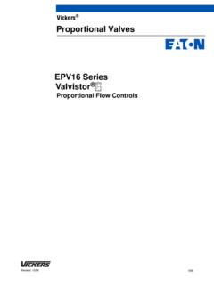
1 General DescriptionVickers Proportional Valves shown in thiscatalog are suitable for workingpressures up to 350 bar (5070 psi) andflow rates up to 300 L/min (79 US gpm).They are designed to provide acontrolled oil flow in proportion to acommand signal, with spool positionfeedback to provide accurate speedcontrol. Hydrostats are available for loadcompensation on sizes 7 and , these Valves can besupplied with or without an integralamplifier built directly onto the version is supplied without theintegral and BenefitsDWide range of spool and flow rateoptionsDSupported by amplifiers and auxiliaryfunction modules from the VickersrangeDElectronic feedback LVDT ensuresaccurate speed controlDCurrent feedback provides inherentprotection from electrical interferenceDVibration and shock testedKAF/HDG5V-5/7/8A range of Proportional directionalvalves with control amplifiers builtdirectly on, and prewired to, the adjustments of gain, spooldeadband compensation, dither andoffset ensure high only electrical inputs required arepower supply (24V)
2 And a voltagecommand signal of "10V. The amplifieris housed in a robust metal connections are via a standard7-pin LEDs give status of Power-on (green) and LVDT failure indication (red).A monitor point allows the function of the amplifier to be checked. Rampfunctions, if required, must be and BenefitsDFactory-sealed adjustments increasevalve-to-valve accuracyDValve and amplifier selected, ordered,delivered and installed as aperformance-tested packageDStandard 24V DC supply with widetolerance bandDStandard "10V DC commandsignalsDInstallation wiring reduced andsimplifiedDStandard 7-pin connectorDLED status indication and monitorpoint help troubleshootingDSimple valve removal andreplacement for serviceDVibration and shock testedDSupported by auxiliary functionmodulesK(A)FDG5V-5/7/8, 1*/3* Series, with Main-Stage Feedback Transducers K(A)HDG5V-5/7/8, 2* Series, with Pilot and Main-Stage Feedback TransducersISO 4401-05, 07 and 08 (ANSI/NFPA-D05, D07 and D08)
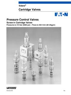
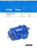
3 Typical cross sectionKHDG5V-7 This product has been designed and tested to meet specific standards outlined in the European ElectromagneticCompatibility Directive (EMC) 89/336/EEC, amended by 91/263/EEC, 92/31/EEC and 93/68/EEC, article 5. Forinstructions on installation requirements to achieve effective protection levels, see this leaflet, the InstallationWiring Practices for VICKERS Electronic Products leaflet 2468 and leaflet 02-123931A which is packed with everyKA valve. Wiring practices relevant to this Directive are indicated by Electromagnetic Compatibility (EMC).PABM6 x 8mm plug part no. 471131. size 7 for internally piloted modelsM5 internal thread forremoval of closure plugRev 1/98GB 2457 VICKERS Proportional ValvesProportional Directional Valves , Two-StagennFunctional Symbols and Application NotesnSee Application Note B, and in Model Code on next Types KHDG5V ShownSimplified symbolModel Types KAHDG5V ShownK(A)FDG5V symbols identical, but omitpilot-stage LVDTsSimplified symbolATBPATBPD etailed symbolDetailed symbolSpool Types7-pinplugATBPATBXYPATBPATBPATBXYPAT BPA pplication NotesA.
4 Main-Spool OptionsSpools shown are meter-in/meter-outtypes. Center-condition options aretypes 2 and Internally Piloted ModelsDiffer from detailed symbols above byomission of plug n and the blocking ofport X by the mating 5 Type 33 Type 2 2 Series type designatorA = Integral amplifierOmit for non-integral amplifierFeedback arrangementF = From main stage onlyH = From pilot and main stagesMounting size code (ISO 4401)5=057=078=08 Spool type, flow rating andmeteringSee Functional Symbols on previouspage p = 5 bar (72 psi) per metering flowpath, B to TSymmetric spoolsFor K*DG5V-5 Valves :2C100N= 100 L/min (26 US gpm)33C80N= 80 L/min (21 US gpm)5C85N= 85 L/min (22 US gpm)For K*DG5V-7 Valves :2C200N= 200 L/min (52 US gpm)33C160N= 160 L/min (42 US gpm)5C200N= 200 L/min (52 US gpm)For K*DG5V-8 Valves :2C300N= 300 L/min (79 US gpm)33C270N= 270 L/min (71 US gpm)5C300N= 300 L/min (79 US gpm)Asymmetric spoolsFirst figure (**N) is flow rating P-A, orA-T ( A port flow).
5 Last figure (N**) isflow rating P-B, or B-T ( B port flow)For K*DG5V-5 Valves :2C70N45= 70 L/min ( USgpm), A port flow45 L/min ( USgpm), B port flow33C65N40= 65 L/min ( USgpm), A port flow40 L/min ( USgpm), B port flowFor K*DG5V-7 Valves :2C150N85= 150 L/min (40 US gpm), A port flow85 L/min ( USgpm), B port flow33C130N65 = 130 L/min ( USgpm), A port flow65 L/min ( USgpm), B port flowFor K*DG5V-8 Valves :2C280N200 = 280 L/min (74 US gpm), A port flow200 L/min (52 US gpm), B port flow33C250N170 = 250 L/min (66 US gpm), A port flow170 L/min (45 US gpm), B port flowPilot supplyEX = External through integral reducerX = Internal through integral reducerSolenoid electrical connectorU1 = ISO 4400/DIN 43650, non-integralamplifier type onlyF = Flying lead, integral amplifier typeonlyElectrical connection(KAF Valves only)PD7 = 7-pin connector with Warning note number10 series for K(A)FDG5V-7/8 models20 series for K(A)H models30 series for K(A)FDG5V-5modelsSubject to change.
6 Installationdimensions unaltered for designnumbers *0 to *9 and LVDT PlugsSupplied with Code51** - C - **K**- * -- ** -34678(A)(E)DG5V*-X - VM- H1 -12345678 WarningTo conform to the EC Electromagnetic Compatibility directive (EMC) this KA valve must be fitted with a metal 7-pinplug. The screen of the cable must be securely connected to the shell of the metal connector. A suitable IP67 ratedconnector is available from VICKERS , part no. 934939. Alternatively a non IP67 rated connector is available fromITT-Cannon, part 02 COM-E 14S A7 the cable must be fitted with a ferrite EMC suppression core not more than 4cm from the connectorreferred to above. Suitable types include Farnell 535-898 or Farnell 535-904 which snap fit over the plastic plug, part number 694534, is only suitable for use in a sealed electromagnetic environment or outside ofthe European Community.
7 3 Operating Data 4 Performance data is typical with fluid at 36 cSt (168 SUS) and 50_C (122_F) while using the basic VICKERS power and KAF/HDG5V ValvesRelative duty factorContinuous rating (ED = 100%)Hysteresis, with flow through P-A-B-T, p = 5 bar (72 psi) per metering path (P-A or B-T):KFDG5 VKHDG5V<2%<1%Step input response, with flow through P-A-B-T, p = 5 bar (72 psi) per metering path, P-ARequired flow step:K(A)FDG5V-50 to 100%100% to 0+90 to 90%K(A)FDG5V-70 to 100%100% to 0+90 to 90%K(A)FDG5V-80 to 100%100% to 0+90 to 90%K(A)HDG5V-50 to 100%100% to 0+90 to 90%K(A)HDG5V-70 to 100%100% to 0+90 to 90%K(A)HDG5V-80 to 100%100% to 0+90 to 90%Time to reach 90% of required step:30 ms ( )24 ms ( )34 ms ( )50 ms ( )54 ms ( )61 ms ( )67 ms ( )56 ms ( )75 ms ( )24 ms ( )23 ms ( )35 ms ( )24 ms ( )23 ms ( )36 ms ( )37 ms ( )36 ms ( )57 ms ( )MassKFDG5V-5 KAFDG5V-5 KFDG5V-7 KAFDG5V-7 KFDG5V-8 KAFDG5V-8 KHDG5V-5 KAHDG5V-5 KHDG5V-7 KAHDG5V-7 KHDG5V-8 KAHDG5V-89,50 kg ( lb) ,90 kg ( lb) ,75 kg ( lb) ,15 kg ( lb) ,00 kg ( lb) ,40 kg ( lb) ,75 kg ( lb) ,15 kg ( lb) ,00 kg ( lb) ,40 kg ( lb) ,25 kg ( lb) ,65 kg ( lb) and start-upSee Further Information 5KF/HDG5V ValvesMax.
8 Current, at 50_C (122_F) ambient2,7 AStanding current, pilot valve at null:KFDG5 VKHDG5V1,4A1,6 ACoil resistance, at 20_C (68_F):KFDG5 VKHDG5V2,8 1,7 Electrical plugs, supplied with valveSee Installation Dimensions KAF/HDG5V ValvesPower supply24V DC (21V to 36V including 10% peak-to-peak max. ripple)max. current 3 ACommand signalInput impedance0 to +10V DC, or 0 to 10V DC, or 10V to +10V DC47 k 7-pin plug connectorPin connections:ABCDEFGP ower supply +vePower 0 VSignal 0V+ve voltage command signal ve voltage command signalMonitor outputProtective groundElectro-magnetic compatibility (EMC):EmissionImmunitySee Important note regarding EMC, five pages onEN 50081-2EN 50082-2 Gain adjustment25 to 125%Zero adjustment"18%Factory-set adjustmentsDeadband, gain, dither and offsetMonitor point signal:Output impedance"10V for full stroke output stage spool10 k Power stage PWM frequency2 kHz nominalRepeatability, valve-to-valve (at factory settings).
9 Flow gain at 100% command signalOptimised by adjustment of deadband compensation, gainand ramp potentiometers on associated VICKERS amplifierProtection:ElectricalReverse polarity protectedRelative humidity85 to 95% at 20 to 70_C (68 to 158_F)Supporting products:Auxiliary electronic modules (DIN-rail mounting):EHA-CON-201-A-1* signal converterEHA-DSG-201-A-1* command signal generatorEHA-RMP-201-A-1* ramp generatorEHA-PID-201-A-1* PID controllerSubplates, size 05, 07 and 08 Mounting bolts Note: If not using VICKERS recommended bolt kits, bolts mustbe to ISO 898 grade or strongerSee catalog 2410 See catalog 2410 See catalog 2410 See catalog 2410 See catalogs 2336, 2337 and 2338 See catalog 2314 6 Maximum Pressures, bar (psi)ModelPilot PressureSourcePortsP, A and BTXYK(A)FDG5V-7/8 Internal or external350 (5000) s350 (5000)350 (5000) s4 (58)K(A)*DG5V-5 External315 (4500)210 (3000)210 (3000) n4 (58)Internal315 (4500) n100 (1450)315 (4500) n4 (58)K(A)HDG5V-7/8 Internal or external350 (5000) n350 (5000)350 (5000) n4 (58)s25 (363) min.
10 Pressure at X for externally piloted models or at P and X for internally piloted (653) min. pressure at X for externally piloted models or at P and X for internally piloted Recommended Flow RatesFor spool types 2C and 33C p = 10 bar (145 psi) for looped flow P-A-B-T (or P-B-A-T)Valve Size/Spool CodeMin. Flow RateL/minin3/minK(A)FDG5V-5-2C100NK(A)FD G5V-5-33C80NK(A)FDG5V-7-2C200NK(A)FDG5V- 7-33C160NK(A)FDG5V-8-2C300NK(A)FDG5V-8-3 3C270N1,01,02,02,03,03,06060121121182182 K(A)HDG5V-5-2C100NK(A)HDG5V-5-33C80NK(A) HDG5V-7-2C200NK(A)HDG5V-7-33C160NK(A)HDG 5V-8-2C300NK(A)HDG5V-8-33C270N0,50,51,01 ,01,51,5303060609191 Power Capacity EnvelopesFlow through P-A-B-T or P-B-A-TKF modelsKH models0150300450600750900L/minUS gpm237210180150120119 Flow rate906039300 Valve pressure drop50004000300020001000350315300200100b arpsi0 Valve pressure dropK(A)FDG5V-5K(A)FDG5V-7K(A)FDG5V-8K(A )HDG5V-5K(A)HDG5V-7K(A)