Transcription of Visual Programming to Embedded ‘C’ Code - ijert.org
1 Visual Programming to Embedded C Code Miss Tejaswi Mahaling Jadhav Dept. of Electronics Engineering, Government polytechnic, Tasgaon, Sangli ( ) India Abstract This paper proposed a Programming system called Flow C . Flow C for creating C program automatically from the flowcharts. Flow C allows designing of ARM-based programs, simply by drawing a flow chart of the desired program. The system will convert it into a C program which is compatible to ARM 7 microcontroller (LPC 2138).Flow chart is an easy way to describe programmer's C allows creating simple microcontroller applications by dragging and dropping icons and connecting them form a flowchart and then converting the flowchart into a C program that is compatible with LPC 2138.
2 KEY WORDS- Flowchart, , Embedded c Programming (LPC 2138) I. INTRODUCTION Computer Programming , now a day has become a required fundamental knowledge for people studies or working in computer field, computer engineering, computer science, information technology etc. Writing a computer program is a difficult task, especially for a beginner. A novice often uses a flowchart as a tool to help him summarize the idea into all necessary steps of solution, but this flowchart needs to be converted to a program for using it with an ARM controller There are more than 50 Programming languages in the world.
3 Some languages are used as general purpose whilst other languages are employed for specific purpose. These computer Programming languages, however, are only the tools used for programmers to communicate with and order the computer to do as they desire. More important thing in writing a program is a design of an algorithm. An inexperienced programmer is always attracted by the syntax of the computer language, and overlooks the significance of algorithm design. The immature programmer who is not familiar with the syntax of the Programming language writes the wrong code frequently.
4 The difficulties of reading and understanding the program in the format of coding is the principal reason of this logical errors. There are two softwares available in markets which have similar functionally 1) structured design using flowchart and 2) Visual Programming using flowchart. Structured design using flowchart (SFC) means is useful for designing and presenting structured flowcharts. SFC is automatically generating pseudo code for a flowchart. Visual Programming using flowchart allows the programmer to write the program in the format of flowchart, then compiles and run, without the coding steps.
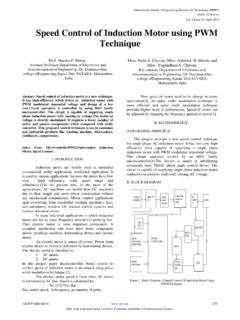
5 This tool aids in the cyclical nature of the algorithm development process as changes can be made rapidly to test new ideas According to survey, the cost of available software in market is very high; but this concept is very useful. So we try to implement this concept. II. SOFTWARE DESIGN The generated C code will be compiled using Keil compiler and test will be taken on simulation software Proteus. Fig 1 blocks of software design The above figure shows the design flow of software. First step is to design graphics user interface in With the help of GUI (graphics user interface) one can able to draw the flowchart.
6 The GUI software will convert it into text file that describe the flowchart This intermediate text file will be converted into actual C code with the help of text to C converter program that is to be written in the C code ( Embedded software) using Keil compiler and simulating the code in the circuit simulator Proteus. The design steps of software as follows: Study of Keil compiler. Write small programs for ARM microcontroller; test these programs in Keil compiler. Write the text file if program will compiled successfully.
7 The text file will be converted into actual C code with the help of converting Code. Compiling the created C code ( Embedded software) using Keil compiler. Study of VB. NET. Design symbols (of flowchart) using TEXT FILE CONVERTING C CODE GRAPHICS USER INTERFACE C CODE PROTUES KEIL COMPILER International Journal of Engineering Research & Technology (IJERT)ISSN: Vol. 4 Issue 06, June-2015316 Using tools of prepare menus for flowchart icon, properties windows, and flowchart windows.
8 Draw the flowchart in Graphics user interface. Software automatically converts flowchart into the intermediate text file. Text file will be converted into actual C codes which are compatible for ARM 7 microcontroller (LPC 2138). Created C code will compile in Keil compiler. Simulate in Protues (Circuit simulator). III. SOFTWARE IMPLEMENTATION It describes how to design graphics user interface in , Steps for conversion of flowchart to text file, how to convert text file to C code using converting program. Graphics user interface Visual studio used tool Assuming is already installed, the next goal is to add the components from the Flowchart package to the Visual Studio toolbox.
9 Some steps to customize the toolbox .Open or create a project of type 'Windows application'. Add reference to the required assemblies to the project The following procedure adds other the property windows forms of symbol to main window. Open the Solution Explorer. Right-click the References section and choose 'Add Reference'. Locate the subfolder appropriate for version of Visual Studio. Select Windows Forms and click the Open button. Add diagram view and diagram object to windows form Now, see icons for the Flow C components in toolbox.
10 As a minimum add a diagram and a diagram view to Windows form. Follow these steps to do that: Open the Visual Studio toolbox. Select and drag the diagram View icon to the form. This creates a diagram view component, which represents the view in document/view architecture. If skipped the steps of above section and if Visual Studio keeps a cached older version of any of the assemblies, the diagram view might fail to load. In such a case, carry out the steps from section and try to add the view component again. When the diagram View is dragged to the form, it automatically adds a diagram component, which represents the document in document/view architecture.