Transcription of VLT® HVAC Drive Programming Guide
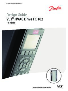
1 MAKING MODERN LIVING POSSIBLEP rogramming GuideVLT HVAC DriveContents1 Copyright, Limitation of Liability and Revision Definitions1-42 How to Local Control How to Operate the GraphicalLCP (GLCP) How to Operate Numeric LCP (NLCP) Quick Menu Function Main Menu Mode2-123 Parameter Parameter Main Menu Main Menu - Operation and Display - Group Main Menu - Load and Motor - Group Main Menu - Brakes - Group Main Menu - Reference/Ramps - Group Main Menu - Limits/Warnings - Group Main Menu - Digital In/Out - Group Main Menu - Analog In/Out - Group Main Menu - Communications and Options - Group Main Menu - Profibus - Group Main Menu - CAN Ser. Com. Bus - Group Main Menu - LonWorks - Group Main Menu - Smart Logic - Group Main Menu - Special Functions -Group Main Menu - Drive Information - Group Main Menu - Data Readouts - Group Main Menu - Data Readouts 2 - Group Main Menu - FC Closed-loop - Group Main Menu - Extended Closed-loop - Group Main Menu - Appl.
2 Functions - Group Main Menu - Time-based Functions - Group 233-139 ContentsVLT HVAC Drive Programming - VLT is a registered Danfoss Main Menu - Application Functions 2 - Group Main Menu - Cascade Controller - Group Main Menu - Analog I/O Option MCB 109 - Group 263-1664 Alarm Warning Extended Status Fault Messages4-85 Parameter Parameter Default 0-** Operation and 1-** Load / 2-** 3-** Reference / 4-** Limits / 5-** Digital In / 6-** Analog In / 8-** Communication and 9-** 10-** CAN 11-** 13-** Smart Logic 14-** Special 15-** FC 16-** Data 18-** Info & 20-** FC 21-** Ext. 22-** Application 23-** Time-based 24-** Application Functions 25-** Cascade 26-** Analog I / O Option MCB 1095-346 Index6-1 ContentsVLT HVAC Drive Programming - VLT is a registered Danfoss trademark1 IntroductionVLT HVAC DriveThis Guide can be used with all VLTHVAC Drive adjustable frequencydrives with software version actual software version numbercan be read from15-43 Software HVAC Drive Programming - VLT is a registered Danfoss , Limitation of Liability andRevision Rights This publication contains information proprietary to accepting and using this manual.
3 The user agrees that theinformation contained herein will be used solely foroperating equipment from Danfoss or equipment from othervendors provided that such equipment is intended forcommunication with Danfoss equipment over a serialcommunication link. This publication is protected under thecopyright laws of Denmark and most other does not warrant that a software program producedaccording to the guidelines provided in this manual willfunction properly in every physical, hardware or Danfoss has tested and reviewed the documen-tation within this manual, Danfoss makes no warranty orrepresentation, neither expressed nor implied, with respectto this documentation, including its quality, performance, orfitness for a particular no event shall Danfoss be liable for direct, indirect, special,incidental, or consequential damages arising out of the use,or the inability to use information contained in this manual.
4 Even if advised of the possibility of such damages. Inparticular, Danfoss is not responsible for any costs, includingbut not limited to those incurred as a result of lost profits orrevenue, loss or damage of equipment, loss of computerprograms, loss of data, the costs to substitute these, or anyclaims by third reserves the right to revise this publication at anytime and to make changes to its contents without priornotice or any obligation to notify former or present users ofsuch revisions or used in this !Indicates something to be noted by the a potentially hazardous situation which, if notavoided, may result in minor or moderate injury orequipment a potentially hazardous situation which, if notavoided, could result in death or serious injury.
5 *Indicates default settingIntroductionVLT HVAC Drive Programming - VLT is a registered Danfoss Alternating currentACAmerican wire gaugeAWGA mpere/AMPAA utomatic Motor AdaptationAMAC urrent limitILIMD egrees Celsius CDirect currentDCDrive DependentD-TYPEE lectro Magnetic CompatibilityEMCE lectronic Thermal RelayETRA djustable Frequency DriveFCGramgHertzHzHorsepowerhpKilohertz kHzLocal Control PanelLCPM etermMillihenry InductancemHMilliamperemAMillisecondmsMi nuteminMotion Control ToolMCTN anofaradnFNewton MetersNmNominal motor currentIM,NNominal motor frequencyfM,NNominal motor powerPM,NNominal motor voltageUM, Extra Low VoltagePELVP rinted Circuit BoardPCBR ated Inverter Output CurrentIINVR evolutions Per MinuteRPMR egenerative terminalsRegenSecondsSynchronous Motor SpeednsTorque limitTLIMV oltsVThe maximum output currentIVLT,MAXThe rated output current supplied by theadjustable frequency driveIVLT,NIntroductionVLT HVAC Drive Programming - VLT is a registered Danfoss Literature for VLT HVAC Drive -Instruction Manual provides thenecessary information for getting the adjustablefrequency Drive up and Manual VLT HVAC Drive High Power.
6 Guide contains all technicalinformation about the adjustable frequency driveand customer design and Guide providesinformation on how to program and includescomplete parameter Instruction, Analog I/O Option MCB 109, Note, Temperature Derating Guide , Configuration Tool MCT 10, the user to configure the adjustablefrequency Drive from a Windows based VLT Energy Box software choose PC Software Download-VLT HVAC Drive Drive Applications, Manual VLT HVAC Drive Profibus, Manual VLT HVAC Drive Device Net, Manual VLT HVAC Drive BACnet, Manual VLT HVAC Drive LonWorks, Manual VLT HVAC Drive Metasys, Manual VLT HVAC Drive FLN, Filter Design Guide , Resistor Design Guide , = Revision numberyy = Language codeDanfoss technical literature is available in print from yourlocal Danfoss Sales Office or online at: + Adjustable frequency Drive :IVLT,MAXM aximum output ,NRated output current supplied by the adjustable , MAXM aximum output :Control commandStart and stop the connected motor by means of LCP anddigital are divided into two in group 1 have higher priority than functions ingroup 1 Reset, Coasting stop, Reset and Coasting stop,Quick stop, DC braking, Stop and the [OFF] 2 Start, Pulse start, Reversing, Start reversing, Jog andFreeze outputMotor:Motor RunningTorque generated on output shaft and speed from zero rpmto max.
7 Speed on frequency when the jog function is activated (viadigital terminals).fMMotor motor motor ,NRated motor frequency (nameplate data).IMMotor current (actual).IM,NRated motor current (nameplate data).nM,NRated motor speed (nameplate data).nsSynchronous motor speedns=2 par. 1 23 60 spar. 1 39 IntroductionVLT HVAC Drive Programming - VLT is a registered Danfoss trademark11PM,NRated motor power (nameplate data in kW or HP).TM,NRated torque (motor).UMInstantaneous motor ,NRated motor voltage (nameplate data).Break-away VLTThe efficiency of the adjustable frequency Drive is defined asthe ratio between the power output and the power commandA stop command belonging to the group 1 controlcommands - see this commandSee Control :Analog ReferenceA signal transmitted to the analog inputs 53 or 54, can bevoltage or ReferenceA signal transmitted to the serial communication ReferenceA defined preset reference to be set from -100% to +100% ofthe reference range.
8 Selection of eight preset references viathe digital ReferenceA pulse frequency signal transmitted to the digital inputs(terminal 29 or 33).RefMAXD etermines the relationship between the reference input at100% full scale value (typically 10V, 20mA) and the resultingreference. The maximum reference value set in3-03 Maximum the relationship between the reference input at0% value (typically 0V, 0mA, 4mA) and the resultingreference. The minimum reference value set in 3-02 :Analog InputsThe analog inputs are used for controlling various functionsof the adjustable frequency are two types of analog inputs:Current input, 0 20 mA and 4 20 mAVoltage input, 0 10 V DC ()Voltage input, -10 +10 V DC ().
9 Analog OutputsThe analog outputs can supply a signal of 0 20 mA, 4 Motor Adaptation, AMAAMA algorithm determines the electrical parameters for theconnected motor at ResistorThe brake resistor is a module capable of absorbing thebraking energy generated in regenerative braking. Thisregenerative braking energy increases the intermediatecircuit voltage and a brake chopper ensures that the poweris transmitted to the brake CharacteristicsConstant torque characteristics used for all applications suchas conveyor belts, displacement pumps and InputsThe digital inputs can be used for controlling variousadjustable frequency Drive OutputsThe adjustable frequency Drive features two solid stateoutputs that can supply a 24 V DC (max.)
10 40 mA) Signal Thermal Relay is a thermal load calculation basedon present load and time. Its purpose is to estimate themotor Hiperface is a registered trademark by HVAC Drive Programming - VLT is a registered Danfoss trademark1-511 InitializingIf initialization is carried out (14-22 Operation Mode), theadjustable frequency Drive returns to the default Duty CycleAn intermittent duty rating refers to a sequence of dutycycles. Each cycle consists of an on-load and an off-loadperiod. The operation can be either periodic duty or non-periodic Local Control Panel makes up a complete interface forcontrol and Programming of the adjustable frequency control panel is detachable and can be installed up to 10ft [3 m] from the adjustable frequency Drive , , in a frontpanel by means of the installation kit significant significant for Mille Circular Mil, an American measuring unit forcable cross-sections.