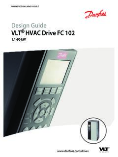
Transcription of VLT® Micro Drive FC 51 - Danfoss
1 Design GuideVLT Micro Drive FC Available Manual and Software Power Factor82 Safety and Disposal CE Aggressive Vibration and Advantages123 Product Control Control Structure Open Local (Hand On) and Remote (Auto On) Control Structure Closed Reference General Aspects of General Aspects of EMC Emission EMC Test Results (Emission) Harmonics Emission Immunity Galvanic Isolation (PELV) Ground Leakage Extreme Running Motor Thermal Protection244 Options and Local Control Panel (LCP) Remote Mounting Kit for FC 51 Remote Mounting Kit Mounting IP21/TYPE 1 Enclosure Type 1 (NEMA)
2 28 ContentsDesign GuideMG02K402 Danfoss A/S 01/2016 All rights Decoupling FC 51 Type 1 Kit Mounting Instruction for M1, M2 and FC 51 Type 1 Kit Mounting Instruction for M4 and FC 51 IP21 Kit Mounting FC 51 Decoupling Plate Mounting Instruction for M1 and FC 51 Decoupling Plate Mounting Instruction for FC 51 Decoupling Plate Mounting Instruction for M4 and FC 51 DIN Rail Kit Mounting Line Filter MCC 107 Installation Special Purpose of Derating for Ambient Derating for Low Air Automatic Adaptations to Ensure Derating for Running at Low Speed375 How to Drive FC Type Ordering Options406 How to
3 Before Side-by-Side Before Commencing Repair Mechanical Electrical Installation in Mains Motor Use of EMC-Correct Grounding of Shielded/Armored Control Residual Current Electrical Power Circuit - Electrical Installation and Control Cables51 ContentsVLT Micro Drive FC 512 Danfoss A/S 01/2016 All rights Control Access to Control Connecting to Control Final Set-Up and Parallel Connection of Motor Installation of Misc. High-voltage Safety Ground Connection567 How to Programming with the LCP 11 or LCP Status Quick Quick Menu Main Quick Transfer of Parameter Settings between Multiple Frequency Readout and Programming of Indexed Initialize the Frequency Converter to Default Settings in two Ways638 RS485 Installation and RS485 Installation and Network Frequency Converter Hardware EMC FC Protocol Network FC Protocol Message Framing Content of a Character (byte)
4 Telegram Telegram Length (LGE) Frequency Converter Address (ADR) Data Control Byte (BCC) The Data The PKE Parameter Number (PNU) Index (IND)70 ContentsDesign GuideMG02K402 Danfoss A/S 01/2016 All rights Parameter Value (PWE) Data Types Supported by the Frequency Process Words (PCD) Modbus RTU Prerequisite What the User Should Already Frequency Converter with Modbus Network Modbus RTU Message Framing Modbus RTU Telegram Start/Stop Address Data CRC Check Coil Register How to Control the Frequency Function Codes Supported by Modbus Modbus Exception How to Access Parameter Storage of Read Coil Status (01 hex) Force/Write Single Coil (05 hex) Force/Write Multiple Coils (0F hex) Read Holding Registers (03 hex) Preset Single Register (06 hex)
5 Preset Multiple Registers (10 hex) FC Drive Control Control Word According to FC Status Word According to FC Profile (STW) Bus Speed Reference Value839 Specifications84 Index91 ContentsVLT Micro Drive FC 514 Danfoss A/S 01/2016 All rights Available LiteratureThis design guide contains the basic information necessaryfor installing and running the frequency technical literature is available in print from localDanfoss Sales Offices or online at: VLT Micro Drive FC 51 Quick Guide VLT Micro Drive FC 51 Programming Guide VLT Micro Drive FC 51 LCP Mounting Instruction VLT Micro Drive FC 51 De-coupling Plate MountingInstruction VLT Micro Drive FC 51 Remote Mounting KitMounting Instruction VLT Micro Drive FC 51 DIN Rail Kit MountingInstruction VLT Micro Drive FC 51 IP21 Kit MountingInstruction VLT Micro Drive FC 51 Nema1 Kit MountingInstruction VLT
6 Micro Drive FC 51 Line Filter MCC 107 Instal-lation Manual and Software VersionThis manual is regularly reviewed and updated. Allsuggestions for improvement are welcome. Table showsthe manual version and the corresponding versionMG02K4 XXMiscellaneous Manual and Software Abbreviations CDegrees celsiusAAmpere/AMPACA lternating currentAMTA utomatic motor tuningAWGA merican wire gaugeDCDirect currentEMCE lectro magnetic compatibilityETRE lectronic thermal relayFCFrequency converterfM,NNominal motor frequencygGramHzHertzIINVR ated inverter output currentILIMC urrent limitIM,NNominal motor currentIVLT,MAXThe maximum output currentIVLT.
7 NThe rated output current supplied by thefrequency converterkHzKilohertzLCPL ocal control panelmMetermAMilliampereMCTM otion control toolmHMillihenry inductanceminMinutemsMillisecondnFNanofa radNmNewton metersnsSynchronous motor speedPM,NNominal motor powerPCBP rinted circuit boardPELVP rotective extra low voltageRPMR evolutions per minuteRegenRegenerative terminalssSecondTLIMT orque limitUM,NNominal motor voltageVVoltTable AbbreviationsIntroductionDesign GuideMG02K402 Danfoss A/S 01/2016 All rights ConverterIVLT,MAXThe maximum output NThe rated output current supplied by the ,MAXThe maximum output commandThe connected motor can be started and stopped with LCPand the digital are divided into 2 in group 1 have higher priority than functions ingroup 1 Reset, coast stop, reset and coast stop, quickstop, DC brake, stop, and the [Off]
8 2 Start, pulse start, reversing, start reversing, jog,and freeze Function motor frequency when the jog function is activated(via digital terminals).fMThe motor maximum motor minimum motor ,NThe rated motor frequency (nameplate data).IMThe motor ,NThe rated motor current (nameplate data).nM,NThe nominal motor speed (nameplate data).PM,NThe rated motor power (nameplate data).UMThe instant motor ,NThe rated motor voltage (nameplate data).Break-away Break-away Torque VLTThe efficiency of the frequency converter is defined as theratio between the power output and the power commandA stop command belonging to the group 1 controlcommands, see Table commandSee Table referenceA signal transmitted to the analog inputs 53 or 54, can bevoltage or referenceA signal transmitted to the serial communication port (FCport).
9 Preset referenceA defined preset reference to be set from -100% to +100%of the reference range. Selection of 8 preset references viathe digital the relationship between the reference input at100% full scale value (typically 10 V, 20 mA) and theresulting reference. The maximum reference value set inparameter 3-03 Maximum the relationship between the reference input at0% value (typically 0 V, 0 mA, 4 mA) and the resultingreference. The minimum reference value set inparameter 3-02 Minimum Micro Drive FC 516 Danfoss A/S 01/2016 All rights inputsThe analog inputs are used for controlling variousfunctions of the frequency are 2 types of analog inputs.
10 Current input, 0 20 mA and 4 20 mA Voltage input, 0 10 V outputsThe analog outputs can supply a signal of 0 20 mA, 4 20mA, or a digital Motor Tuning, AMTAMT algorithm determines the electrical parameters for theconnected motor at resistorThe brake resistor is a module capable of absorbing thebrake power generated in regenerative braking. Thisregenerative brake power increases the DC-link voltage,and a brake chopper ensures that the power is transmittedto the brake characteristicsConstant torque characteristics used for all applicationssuch as conveyor belts, displacement pumps, and inputsThe digital inputs can be used for controlling variousfunctions of the frequency outputsThe frequency
