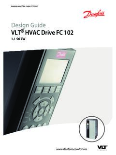
Transcription of VLT® Micro Drive FC 51 Programming Guide - Danfoss
1 MAKING MODERN LIVING POSSIBLEP rogramming GuideVLT Micro DriveContents1 High Voltage Safety Software Version and General IT Avoid unintended Before Commencing Repair Work42 FC Type Code63 How to Programming with MCT 10 Set-up Programming with the LCP 11 or LCP Status Quick Main Menu104 Parameter Parameter Group 0: Parameter Group 1: Parameter Group 2: Parameter Group 3: Parameter Group 4: Parameter Group 5: Digital Parameter Group 6: Analog 6-1* Analog Input Parameter Group 7: Parameter Group 8: 8-8* Bus communication Parameter Group 13: Smart 13-** Programming Parameter Group 14: Special Parameter Group 15: Drive 15-4* Drive Parameter Group 16: Data Readouts48 ContentsVLT Micro Drive FC 51 Programming GuideMG02C602 - VLT is a registered Danfoss trademark15 Parameter Conversion Change during 0-** 1-** 2-** 3-** 4-** 5-** Digital 6-** Analog 7-** 8-** Comm.
2 And 13-** Smart 14-** Special 15-** Drive 16-** Data Readouts626 Alarm, Warning and Extended Status Word65 Index69 ContentsVLT Micro Drive FC 51 Programming Guide2MG02C602 - VLT is a registered Danfoss Voltage WarningWARNINGThe voltage of the frequency converter is dangerouswhenever it is connected to mains. Incorrect installation ofthe motor or frequency converter may cause damage tothe equipment, serious injury or death. Consequently, it isessential to comply with the instructions in this manual aswell as local and national rules and safety InstructionsCAUTIONB efore using functions directly or indirectly influencingpersonal safety ( Safe Stop, Fire Mode or otherfunctions either forcing the motor to stop or attempting tokeep it functioning) a thorough risk analysis and systemtest must be carried through.
3 The system tests mustinclude testing failure modes regarding the controlsignaling (analog and digital signals and serial using Fire Mode, contact Danfoss Make sure the frequency converter is properlyconnected to earth. Do not remove mains connections, motorconnections or other power connections whilethe frequency converter is connected to power. Protect users against supply voltage. Protect the motor against overloading accordingto national and local regulations. The earth leakage current exceeds mA. The [Off] key is not a safety switch. It does notdisconnect the frequency converter from Version and ApprovalsSoftware VersionProgramming GuideVLT Micro DriveFC 51 Series This Programming Guide can be used for all VLT Micro Drive frequency converters with softwareversion software version number can be read in15-43 Software WarningWARNINGELECTRICAL SHOCK HAZARDT ouching the electrical parts may be fatal - even after theequipment has been disconnected from make sure that other voltage inputs have beendisconnected (linkage of DC intermediate circuit).)
4 Be aware that there may be high voltage on the DC linkeven when the LEDs are turned touching any potentially live parts of the frequencyconverter, wait at least 4 min for all time is allowed only if indicated on the nameplatefor the specific Micro Drive FC 51 Programming GuideMG02C602 - VLT is a registered Danfoss trademark311 CAUTIONL eakage CurrentThe earth leakage current from the frequency converterexceeds mA. According to IEC 61800-5-1 a reinforcedProtective Earth connection must be ensured by means ofa min. 10 mm Cu or an additional PE wire - with the samecable cross section as the Mains wiring - must beterminated Current DeviceThis product can cause a DC current in the protectiveconductor.
5 Where a residual current device (RCD) is usedfor extra protection, only an RCD of Type B (time delayed)shall be used on the supply side of this product. See alsoDanfoss Application Note on RCD, earthing of the frequency converter and the useof RCDs must always follow national and local overload protection is possible by setting 1-90 MotorThermal Protection to the value ETR trip. For the NorthAmerican market: ETR functions provide class 20 motoroverload protection, in accordance with in high altitudes:For altitudes above 2 km, please contact Danfoss MainsCAUTIONIT MainsInstallation on isolated mains source, IT supply voltage allowed when connected to mains:440 an option, Danfoss offers line filters for improvedharmonics unintended StartWhile the frequency converter is connected to mains, themotor can be started/stopped using digital commands, buscommands, references or via the Local Control Panel.
6 Disconnect the frequency converter from mainsto avoid unintended start of any motors. To avoid unintended start, always press the [Off]key before changing Instruction Equipment containing electrical componentsmust not be disposed of together withdomestic must be separately collected with electricaland electronic waste according to local andcurrently valid Commencing Repair FC 51 from mains (and external DCsupply, if present). for 4 minutes (M1, M2 and M3) and 15 min(M4 and M5) for discharge of the DC bus terminals and brake terminals(if present) motor cableSafetyVLT Micro Drive FC 51 Programming Guide4MG02C602 - VLT is a registered Danfoss IdentificationThe nameplate sticker is located on the top of eachfrequency converter and shows the ratings, serial number,warnings catalog number, and other relevant data for eachunit.
7 See Table for details, how to read the type This Example Shows the Nameplate StickerIntroductionVLT Micro Drive FC 51 Programming GuideMG02C602 - VLT is a registered Danfoss CodeIllustration choiceProduct group1-3 Frequency convertersSeries and product type4-6 Micro DrivePower kWMains voltage11-12S2: Single phase 200-240 V ACT 2: Three phase 200-240 V ACT 4: Three phase 380-480 V ACEnclosure13-15IP20/ChassisRFI filter16-17HX: No RFI filterH1: RFI filter class A1/BH3:RFI filter A1/B (reduced cable length*)Brake18B: Brake chopper included (from kW and up)X: No brake chopper includedDisplay19X: No Local Control PanelN: Numerical Local Control Panel (LCP)P: Numerical Local Control Panel (LCP)) with potentiometerCoating PCB20C: Coated PCBX.
8 No coated PCBM ains option21X: No mains optionAdaptation A22X: No adaptationAdaptation B23X: No adaptationSoftware release24-27 SXXX: Latest release - std. softwareTable Type Code Description*See VLT Micro Drive Design Guide , MG02 KIntroductionVLT Micro Drive FC 51 Programming Guide6MG02C602 - VLT is a registered Danfoss and ApprovalsSymbols used in this Programming following symbols are used in this a potentially hazardous situation which, if notavoided, could result in death or serious a potentially hazardous situation which, if notavoided, may result in minor or moderate injury. It mayalso be used to alert against unsafe a situation that may result in equipment orproperty-damage-only and Standards AbbreviationsTermsSI-unitsI-P unitsaAccelerationm/s2ft/s2 AWGA merican wire gauge Auto TuneAutomatic Motor Tuning CCelsius ICurrentAAmpILIMC urrent limit IT mainsMains supply with star point in transformer floating to ground JouleEnergyJ=N mft-lb, Btu FFahrenheit FCfrequency converter fFrequencyHzHzkHzKilohertzkHzkHzLCPL ocal Control Panel mAMilliampere msMillisecond minMinute MCTM otion Control Tool M-TYPEM otor Type Dependent NmNewton Metres in-lbsIM,NNominal motor current fM,NNominal motor frequency PM.
9 NNominal motor power UM,NNominal motor voltage PELVP rotective Extra Low Voltage WattPowerWBtu/hr, hpPascalPressurePa = N/m psi, psf, ft of waterIINVR ated Inverter Output Current RPMR evolutions Per Minute sSecond SRSize Related TTemperatureCFtTimess,hrTLIMT orque limit UVoltageVVTable Abbreviation and Standards TableIntroductionVLT Micro Drive FC 51 Programming GuideMG02C602 - VLT is a registered Danfoss How to with MCT 10 Set-upSoftwareThe frequency converter can be programmed from a PCvia RS-485 com-port by installing the MCT 10 software can either be ordered using code number130B1000 or downloaded from the Danfoss Web to the manual for Motion Control Tools with the LCP 11 or LCP12 The LCP is divided into four functional keys and indicator lights (LEDs).
10 Illustration LCP 12 with PotentiometerIllustration LCP 11 without PotentiometerThe displayDifferent information can be read from the number shows the active set-up and the edit set-up. If the same set-up acts as both active and edit set-up,only that set-up number is shown (factory setting).When active and edit set-up differ, both numbers areshown in the display (Set-up 12). The number flashing,indicates the edit Indicating Set-upThe small digits to the left are the selected Indicating Selected Parameter NumberThe large digits in the middle of the display show thevalue of the selected Indicating Value of Selected ParameterThe right side of the display shows the unit of the selectedparameter.