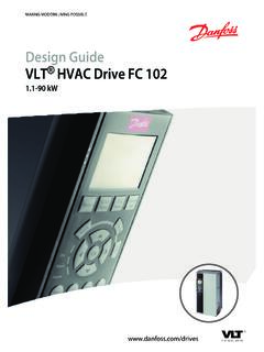
Transcription of VLT® PROFIBUS DP MCA 101
1 MAKING MODERN LIVING POSSIBLEP rogramming GuideVLT PROFIBUS DP MCA 101 VLT Frequency converter Series FC 102 FC 103 FC 202FC 301/302 FCD 302 FCP 106 FCM Purpose of the Additional Document and Software Product Approvals and Symbols, Abbreviations, and Conventions52 Safety Qualified Safety Precautions63 Configure the PROFIBUS Configure the GSD Configure the Frequency Frequency converter LEDs124 PPO Process Process Control Process Status Reference Process Control Influence of the Digital Input Terminals on FC Control Control PROFI drive Control Control Word According to PROFI drive Profile (CTW) Status Word According to PROFI drive Profile (STW) PROFI drive State Transition Danfoss FC Control Control Word According to FC Profile (CTW) Status Word According to FC Profile (STW) Synchronize and Freeze/Unfreeze24 ContentsProgramming GuideMG37G202 Danfoss A/S 01/2016 All rights Parameter Parameter Access in DP-V1 Parameter PCV Parameter PROFIBUS DP Parameter and Data Type336 8-** PROFIBUS 9-** and 16-** PROFIBUS PROFIBUS -specific Parameter List467 Application Example 1: Process Data with PPO Type Example 2: Control Word Telegram using PPO Example 3: Status Word Telegram using PPO Example 4.
2 PLC Programming518 No Response to Control Warnings and Fault Messages via DP Extended Diagnosis59 Index60 ContentsVLT PROFIBUS DP MCA 1012 Danfoss A/S 01/2016 All rights Purpose of the ManualThe VLT PROFIBUS DP MCA 101 Programming Guideprovides information about: Configuring the system. Controlling the frequency converter . Parameter access. Programming. Troubleshooting. Typical application programming guide is intended for use by qualifiedpersonnel familiar with the VLT frequency converter , withPROFIBUS technology, and with the PC or PLC used as amaster in the the instructions before programming and follow theprocedures in this is a registered Additional ResourcesResources available for the frequency converters andoptional equipment: The VLT Operating Instructions provide thenecessary information for getting the frequencyconverter up and running.
3 The VLT Design Guide provides detailedinformation about capabilities and functionalityto design motor control systems. The VLT Programming Guide provides greaterdetail on working with parameters and manyapplication examples. The VLT PROFIBUS DP MCA 101 Installation Guideprovides information about installing thePROFIBUS and troubleshooting. The VLT PROFIBUS DP MCA 101 ProgrammingGuide provides information about configuring thesystem, controlling the frequency converter ,parameter access, programming, troubleshooting,and some typical application publications and manuals are availablefrom Danfoss. See for Document and Software VersionThis manual is regularly reviewed and updated.
4 Allsuggestions for improvement are welcome. Table showsthe document version and the corresponding Information about VLT DriveMotorFCP 106/FCM 106 added. New feature for fast PCD communi-cation for MCO Document and Software Product of PROFIBUS DP-V1 2 different state machines can be selected:PROFI drive profile or Danfoss FC profile. Communication using PROFIBUS DP-V1, masterclass 1, and master class 2. Backward compatibility: New protocol extensionsretain all the functions of the previous versions. Intelligent base for future technologies such asOPC, FDT/DTM, PROFINET. Bus timeout reaction. PLC/CPU stop reaction. 8 PPO types available. Numerous relevant process data (PCD) typesavailable.
5 Automatic detection of baud rate and PPO type. Extended diagnosis available. Alarms and warnings available as text messageswithin the PLC. Configuration via MCT 10 Set-up Software. Equally long bus cycle time configurable in PLCsystem. Improved network efficiency, since the cyclicparameter channel is no longer required. Short bus cycle times compared to industrialEthernet. Backwards compatibility with GuideMG37G202 Danfoss A/S 01/2016 All rights OverviewPROFIBUSPROFIBUS is an international standard for fieldbuscommunication in automation technology (IEC 61158 andIEC 61784). The member companies of the PROFIBUSI nternational User Community support the information about PROFIBUS and downloads forPROFIBUS DP and the PROFI drive profile, refer DP-V1 The PROFIBUS DP protocol enables communicationbetween PROFIBUS masters and communication via MCT 10 Set-up communication PLC communicates with telegrams of constantlength.
6 Fits time-critical requirements. Cyclic transmission via PPO types. Extended PROFIBUS DP-V0 Features of a master class 1 connection: Cyclic data exchange (DP-V0). Acyclic read/write on parameters. Extended acyclic connection is fixed and cannot be changedduring of a master class 2 connection: Initiate/abort acyclic connection. Acyclic read/write on acyclic connection can be established (initiated) orremoved (aborted) dynamically even when a master class 1is active on the network. Use the DP-V1 acyclic connectionfor general parameter access as an alternative to the PCVparameter class 1PC toolMaster class 2 Illustration PROFIBUS DP-V1 The PROFIBUS DP extension DP-V1 allows acyclic as well ascyclic data communication.
7 This feature can be used by aDP master class 1, for example PLC, as well as a DP masterclass 2, for example PC Approvals and CertificationsMore approvals and certifications are available. For moreinformation, contact a local Danfoss PROFIBUS DP MCA 1014 Danfoss A/S 01/2016 All rights Symbols, Abbreviations, andConventionsCANC ontroller area networkCTWC ontrol wordDPDistributed peripheryDTM DUData unitEEPROME lectrical erasable programmable read-only memoryEMCE lectromagnetic compatibilityFDTF ield device toolHMI INDSub indexLCDL iquid crystal displayLCPL ocal control panelLEDL ight emitting diodeMAVMain actual valueMC1 Master class 1MC2 Master class 2 MRVMain reference valueOPC PCPersonal computerPCDP rocess dataPCAP arameter characteristicsPCVP arameter characteristics valuePDUP rotocol data unitPLCP rogrammable logic controlPNUP arameter numberPPOP arameter-process dataPVAP arameter valueRCRequest/response characteristicsSAPS ervice access pointSMPS pontaneous
8 MessageSTWS tatus wordTable Symbols and AbbreviationsConventionsNumbered lists indicate lists indicate other information and description of text indicates: Cross-reference. Link. Footnote. Parameter name. Parameter group name. Parameter option.* indicates a default setting in a GuideMG37G202 Danfoss A/S 01/2016 All rights Safety SymbolsThe following symbols are used in this manual:WARNINGI ndicates a potentially hazardous situation that couldresult in death or serious a potentially hazardous situation that couldresult in minor or moderate injury. It can also be used toalert against unsafe important information, including situations thatcan result in damage to equipment or Qualified PersonnelCorrect and reliable transport, storage, installation,operation, and maintenance are required for the trouble-free and safe operation of the frequency converter .
9 Onlyqualified personnel are allowed to install and operate personnel are defined as trained staff, who areauthorized to install, commission, and maintain equipment,systems, and circuits in accordance with pertinent laws andregulations. Also, the qualified personnel must be familiarwith the instructions and safety measures described inthese operating Safety PrecautionsWARNINGHIGH VOLTAGEF requency converters contain high voltage whenconnected to AC mains input, DC supply, or load to perform installation, start-up, and maintenanceby qualified personnel can result in death or seriousinjury. Only qualified personnel must perform instal-lation, start-up, and STARTWhen the frequency converter is connected to AC mains,DC supply, or load sharing, the motor may start at anytime.
10 Unintended start during programming, service, orrepair work can result in death, serious injury, orproperty damage. The motor can start with an externalswitch, a fieldbus command, an input reference signalfrom the LCP or LOP, via remote operation using MCT 10 Set-up Software, or after a cleared fault prevent unintended motor start: Press [Off/Reset] on the LCP beforeprogramming parameters. Disconnect the frequency converter from themains. Completely wire and assemble the frequencyconverter, motor, and any driven equipmentbefore connecting the frequency converter toAC mains, DC supply, or load TIMEThe frequency converter contains DC-link capacitors,which can remain charged even when the frequencyconverter is not powered.
