Transcription of VME420 Multi-functional monitoring relays for ... - bender.ro
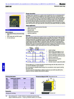
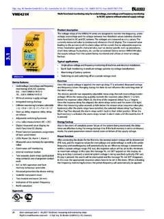
1 W. Bender GmbH & Co. KG Londorfer Str. 65 35305 Gr nberg Tel.: 06401 807-0 Fax: 06401 807-259 Right to modifications reserved ! W. Bender GmbH & Co. KG, Germany24 Main catalogue part 3 / Electronic measuring and monitoring relays VME420 VME420 Device features monitoring AC/DC systems for under-voltage, overvoltage and frequency in the voltage range of V Different monitoring functions selectable < U, > U or < U/> U, < f, > f or < f / > f Start-up delay, response delay, delay on release Adjustable switching hysteresis value measurement (AC + DC) Digital measured value display via Multi-functional LC display Preset function (automatic assignment of basic parameters) LEDs: Power On, Alarm 1, Alarm 2 Measured value memory for operating value Continuous self monitoring Internal test/reset button Two separate alarm relays (gold-plated relay contacts), one changeover contact each N/C or N/O operation and fault memory behaviour selectable Password protection for device setting Sealable transparent cover Two-module enclosure (36 mm) Indication of the system frequency RoHS-compliantApprovalsProduct descriptionThe voltage relays of the VME420 series are designed to monitor the frequency, under-voltage, overvoltage and the voltage between two threshold values (window discriminator function) in AC and DC systems.
2 The voltages are measured as values. The currently measured value is continuously shown on the LC display. The measured value leading to the activation of the alarm relays will be stored. Due to adjustable response times, installation-specific characteristics, such as device-specific start-up procedures, short-time voltage fluctuations, etc. can be considered . Device version VME420 requires an external supply applications Single-phase voltage and frequency monitoring of machines and electrical installations Earth fault monitoring in medium-voltage systems via voltage transformers monitoring of battery systems Switching on and switching off at a certain voltage levelFunctionOnce the supply voltage is applied, the start-up delay t is activated. Measured voltage and frequency values changing during this time do not influence the switching state of the alarm devices provide two separately adjustable measuring channels (overvoltage/under-voltage).
3 When the measuring quantity exceeds the response value (Alarm 1) or falls below the response value (Alarm 2), the time of the response delays ton 1/2 begins. Once the response delay has elapsed, the alarm relays switch and the alarm LEDs light. When the measuring value exceeds or falls below the release value (response value plus hysteresis) after the alarm relays have switched, the selected release delay toff begins. When toff has elapsed, the alarm relays switch back to their initial the fault memory is activated, the alarm relays remain in the alarm state until the reset button R is pressed. When the fault memory is set to continuous mode, the alarm parameters remain stored, even on failure of the supply functionAfter connecting the device for the first time, the nominal system voltage will be determined (PrE run), and the response values for overvoltage and undervoltage as well as for under-frequency and overfrequency will automatically be set.
4 When no voltage is determined within a nominal system voltage range (PrE run), the response values will be set to the minimum or maximum voltage. In this case, the message AL not SET appears on the display. As long as no key is pressed, a nominal system voltage is being searched cyclically (PrE run). If a key is pressed, the search will be interrupted and the message AL not SET disappears. In this case, the appropriate response values have to be set in the menu. When activating the frequency monitoring function, the preset frequency will automatically be monitoring relays for overvoltage, undervoltage and frequency monitoring in AC/DC systems with external supply Main catalogue part 3 / Electronic measuring and monitoring relays 25 Wiring diagram1 - Connection to the system/load being monitored2 - Supply voltage US (see ordering information) 3 - Alarm relay K1: Configurable f < U / > U / < f / > f / ERROR4 - Alarm relay K2: Configurable f < U / > U / < f / > f / ERROR5 - Line protection according to IEC 60364-4-43 A 6 A fuse is recommended.
5 If being supplied from an IT system, both lines have to be protected by a elements1 - LED Power On ON (green); lights when supply voltage is applied and flashes in the event of system fault alarm. 2 - Alarm LED AL1 (yellow), lights when the set response value > U / < f / > f is exceeded and flashes in the event of system fault - Alarm LED AL2 (yellow), lights when the value falls below the set response value< U / < f / > f and flashes in the event system fault - Multi-functional LC - Test button T : UP key: To change the measured value display, move downwards in the menu or change parameters. To call up the self test: Press the key > s6 - Reset R button: DOWN key: To change the measured value display, move downwards in the menu or change parameters.
6 Delete stored alarms: Press the key > s 7 - MENU key: Enter key: To confirm the measured value display or change parameters. To call up the menu system : Press the key> s Press ESC key > s: to abort an action or to return to the previous menu level .1452367155234 monitoring relays for overvoltage, undervoltage and frequency monitoring Main catalogue part 3 / Electronic measuring and monitoring relays Timing diagram voltage monitoringt - Start-up delaytan - Response timetoff - Delay on releaseMonitoring relays for overvoltage, undervoltage and frequency monitoring VME420 Dimension diagram XM420 Dimensions in mmOpen the front plate cover in direction of arrow!Screw fixingNote: The upper mounting clip must be ordered separately (see ordering information).
7 Main catalogue part 3 / Electronic measuring and monitoring relays 27 Insulation coordination acc. to IEC 60664-1 / IEC 60664-3 Rated insulation voltage 250 VRated impulse voltage/pollution degree kV / IIIP rotective separation (reinforced insulation) between: (A1, A2) - (U1/+, U2/-) - (11-12-14) - (21-22-24)Voltage test acc. to IEC 61010-1 kVSupply voltageVME420-D-1:Supply voltage US AC V / DC VFrequency range US HzVME420-D-2:Supply voltage US AC / DC VFrequency range US HzPower consumption VAMeasuring circuitMeasuring range ( value) AC / DC VRated frequency fn DC, HzFrequency display range HzResponse valuesUndervoltage < U (Alarm 2) AC / DC VOvervoltage > U (Alarm 1) AC / DC VResolution of setting U V VResolution of setting U V 1 VPreset function:Undervoltage < U = ( Un):*for Un = 230 V / 120 V/ 60 V/ 24 V 196 V / 102 V / 51 V / VOvervoltage > U = ( Un).
8 *for Un = 230 V / 120 V/ 60 V/ 24 V 253 V / 132 V / 66 V / VRelative percentage error voltage at 50/60 Hz %, 2 digitsRelative percentage error in the voltage range Hz 3 %, 2 digitsHysteresis U % (5 %)*Underfrequency < Hz HzOverfrequency > Hz HzResolution of setting f Hz HzResolution of setting f Hz 1 HzPreset function:Underfrequency for fn = Hz / 50 Hz / 60 Hz / 400 Hz Hz / Hz / Hz / 399 HzOverfrequency for fn = Hz / 50 Hz / 60 Hz / 400 Hz Hz / Hz / Hz / 401 HzHysteresis frequency Hys Hz Hz ( Hz)*Relative percentage error in the frequency range Hz %, 1 digitsSpecified timeStart-up delay t s (0 s)*Response delay ton1/2 s (0 s)*Delay on release toff s ( s)*Operating time voltage tae DC/AC Hz: 130 ms, AC Hz: 70 msOperating time frequency tae AC Hz.
9 310 msResponse time tan tan = tae + ton1/2 Recovery time tb 300 ms Displays, memoryDisplay LC display, Multi-functional , not illuminatedDisplay range measured value AC/DC VOperating error voltage at 50/60 Hz %, 2 digitsRelative percentage error in the voltage range Hz 3 %, 2 digitsRelative percentage error in the frequency range Hz %, 1 digitsHistory memory (HiS) for the first alarm value data record measured valuesPassword off / (off )*Fault memory (M) alarm relay on / off / con (on)*Switching elementsNumber of changeover contacts 2 x 1 (K1, K2)Operating principle N/C or N/O operation K2:Err, < U, > U, < Hz, > Hz (undervoltage < U: N/C operation )* K1: Err, < U, > U, < Hz, > Hz (overvoltage > U: N/O operation )*Electrical service life under rated operating conditions, number of cycles 10 000 Contact data acc.
10 To IEC 60947-5-1:Utilization category AC-13 AC-14 DC-12 DC-12 DC-12 Rated operational voltage 230 V 230 V 24 V 110 V 220 VRated operational current 5 A 3 A 1 A A AMinimum contact load 1 mA at AC / DC 10 VEnvironment / EMCEMC IEC 61326-1 Operating temperature -25 +55 CClassification of climatic conditions acc. to IEC 60721:Stationary use (IEC 60721-3-3) 3K5 (except condensation and formation of ice)Transport (IEC 60721-3-2) 2K3 (except condensation and formation of ice)Storage (IEC 60721-3-1) 1K4 (except condensation and formation of ice)Classification of mechanical conditions acc. to IEC 60721:Stationary use (IEC 60721-3-3) 3M4 Transport (IEC 60721-3-2) 2M2 Storage (IEC 60721-3-1) 1M3 ConnectionConnection screw terminalsConnection properties:rigid/ flexible / conductor sizes / mm2 / AWG connection (2 conductors with the same cross section).