Transcription of ZUE150 DB en 20070620 - BENDER
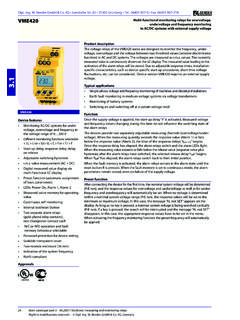
1 W. BENDER GmbH & Co. KG Londorfer Str. 65 35305 Gr nberg Tel.: 06401 807-0 Fax: 06401 807-259 Right to modifications reserved ! W. BENDER GmbH & Co. KG, Germany106 Main catalogue part 3 / Electronic measuring and monitoring relays ZUE150 Automatic restart relayDevice features Adjustable ON delay and stored energy time Alarm relay with one N/O contact 45 mm enclosureProduct descriptionA voltage drop or interruption in control circuits of production lines or conveying systems the processes of which are susceptible to interruptions may cause considerable costs. Therefore, it is often desired to restart the loads automatically after voltage interruptions. In order to avoid that all loads are connected to supply at the same time, the loads have to be connected at intervals. When the duration of undervoltage (power supply failure) exceeds the adjusted maximum restart time, an automatic restart is to be prevented.
2 The automatic restart relay ZUE150 meets these requirements by measuring the voltage value and by giving a start signal after the continuously adjustable ON delay has applications Chemical and und petrochemical industries Plastics processing Industrial mills Mechanical engineering Lighting equipmentFunctionWhen the power supply is interrupted or when the voltage falls below the response value, for a period not exceeding the adjusted stored energy time, the contact 11/14 closes on voltage recovery after the adjusted ON delay has elapsed, enabling the external contactor to operate, if wired accordingly. If the duration of power supply failure exceeds the adjusted stored energy time, there will be no automatic restart. The device can be switched on without delay.
3 The device can be switched on manually at any time, independent of the ON delay. Pressing the external OFF button will cause a tripping of the external contactor so that an automatic restart is prevented even in the case of voltage failure. ZUE150123451 - System voltage2 - Relay contact (with option U3 the relay is activated for 200 ms only)3 - External ON button (button pressed)4 - External OFF button (button pressed)5 - External contactor K2tAB - Adjusted stored energy timetAN - Adjusted ON delaytu - Duration of power supply interruptionIf the duration of tu (1) is below the adjusted stored energy time, the relay contact K1 clo-ses when the ON delay tAN has tu (2) exceeds the adjusted stored energy time, no automatic restart signal is sent by the restart limit values for voltage drop or voltage recovery are set to 65% resp.
4 80% of the respective nominal voltage (internal device setting).Ordering informationType Nominal system voltage Un Option Art. AC 50 Hz 230 V B 936 156 ZUE150 AC 50 Hz 110 V B 936 600 ZUE150 -U2 AC 50 Hz 220 V U2 B 936 152 ZUE150 AC 50 Hz 240 V B 936 601 ZUE150 AC 60 Hz 110 V B 936 604 ZUE150 -U3 AC 50 Hz 230 V U3 B 936 158 ZUE150 AC 60 Hz 110 V U1 + U3 B 936 202 Mounting rail for screw fixing B 974 728 AccessoriesDimension diagram X150 Dimensions in Main catalogue part 3 / Electronic measuring and monitoring relays 107 Wiring diagramTechnical data automatic restart relay ZUE150 Insulation coordination acc. to IEC 60664-1 Rated insulation voltage AC 250 VRated impulse voltage/pollution degree kV/3 System being monitoredPower consumption Terminal U1 3 VA Terminal 11, 14 VAMeasuring circuitNominal system voltage see ordering information Frequency fn AC 50/60 HzOperating range UnResponse valuesUndervoltage level x UnThreshold value for voltage return x UnTime setting scale continuously adjustable domains for ON delay tAN x ( s) and stored energy time tAB x 1 ( s) x 10 ( s)
5 Switching elementsNumber of contacts 1 N/O contactElectrical service life, number of cycles 12000 Contact class IEC 60255 Part 0-20 IIBR ated contact voltage AC 250 V/DC 300 VLimited making capacity AC/DC 5 ABreaking capacity 2 A, AC 230 V, cos phi A, DC 220 V, L/R = sEnvironment / EMCEMC immunity acc. to IEC 61000-6-2 EMC emission acc. to IEC 61000-6-4 Shock resistance IEC 60068-2-27 (during operation) 15 g/11 ms Bumping IEC 60068-2-29 (during transport) 40 g/6 ms Vibration resistance IEC 60068-2-6 (during operation) 1 g / Hz Vibration resistance IEC 60068-2-6 (during transport) 2 g / Hz Ambient temperature, during operation +60 C Ambient temperature, during storage +70 C Climatic class acc. to IEC 60721-3-3 3K5 (except condensation and formation of ice)OtherOperating mode continuous operationMounting any positionConnection Flat terminals with self-lifting clamp washersConnection properties single wire 2 x ( ) mm2flexible with end ferrules 2 x ( ) mm2 Degree of protection, internal components (IEC 60529) IP50 Degree of protection, terminals/with terminal covers (IEC 60529) IP10/IP20 DIN rail mounting acc.
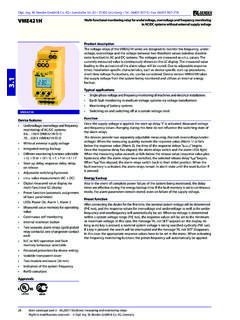
6 To IEC 60715 Flammability class UL94V-0 Operating manual BP308005 Weight 400 g123541 - Three-position switch to set the multiplying factor for tAN2 - Three-position switch to set the multiplying factor for tAB3 - Potentiometer for ON delay tAN setting4 - Potentiometer for setting the stored energy time tAB 5 - Alarm relay with one N/O contactF - A 6 A fuse - Potentiometer for continuous ON delay setting ranking on a scale of By means of a three-position switch, the time domain can be selected between (x ), s (x 1) and s (x 10).tAB - Potentiometer for continuous stored energy time adjustment ranking on a scale of The time domain can be selected in the same way as described for the duration of undervoltage/voltage interruption exceeds the adjusted time tAB, an automatic restart is U1 Terminals U21 and U22: Potential-free optocoupler output for signalling the restart : AC 140 V / DC 200 VUlow max at 30 mA = VOption U2 If the terminals U31 and U32 are connected to an N/O contact of the OFF button, disconnection is possible in a deenergized sys-tem (no automatic restart).
7 Option U3 Reclosure contact with 200 ms contact restart relay