Transcription of Warm - mesteksa.com
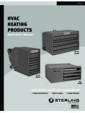
1 Indirect FiredDuct FurnacesIndirect FiredDuct Furnaces WarmTempriteKeeps YouTGGTD-1 Technical Guide for: GTD Two Pass GTDM Four PassGTDM SeriesGTD Series2 TempriteKeeps YouWarmTempriteKeeps YouWarmIn the business of industrial heating, efficient and low-cost operation is essential. Tempritekeeps you warm for 1963, Temprite has been providing cost-effective, reliable heating solutions. Our provenIndirect fired duct Furnaces adds warm clean air to your work environment, but without theproducts of combustion in the Technical Guide will help you choose an Temprite Indirect fired Gas duct furnace toprovide efficient, cost-effective heating and ventilation for your facility.
2 The Guide covers: Technical Specifications Configure the right system components ( , motors, drive,filter, options, etc.) to meet your needs. Model GTD for two pass units Model GTDM for four pass units Installation Information Plan details of on-site installation (dimensions, gas piping, etc.).If you have questions, please contact Temprite s Customer Service Department at ll be glad to FiredDuct FurnacesTechnical Guide3 Engineering Data GTD 4 Dimensions GTD 5 Pressure Drop ChartsGTD-160 duct 6 GTD-320 duct 7 GTD-480 duct 8 GTD-800 duct 9 GTD-1120 duct 10 Typical Gas Piping Layout GTD 11 Typical Wiring DiagramGTD-160 & 13 GTD-800 & 14 Guide Specification GTD 15 Engineering Data GTDM 16-17 Dimensions GTDM 18-19 Pressure Drop ChartsGTDM-25 40 duct 20 GTDM-45 55 duct 21 GTDM-65 75 duct 22 GTDM-85 100 duct 23 GTDM-125 175 duct 24 GTDM-200 250 duct 25 GTDM-275 300 duct
3 26 GTDM-325 400 duct 27 GTDM-500 600 duct 28 Typical Gas Piping Layout GTDM 29 Typical Wiring 30 Guide Specification GTDM 314 Model SizeInput (Maximum)Output (B)Input (Minimum)Natural Gas at 1,000 Gas Std. Pipe Size (7 )Manifold PressureOrifice SizePropane Fuel at 2,500 P. Gas Std. Pipe Size (11 )Manifold PressureOrifice SizeMinimum AirflowMaximum AirflowCombustion Air Requirements (CFM)Recommended Minimum Stack Size DiameterMaximum Vent Length - Equivalent Length (Ft)Primary Heating Surface Sq. FeetSecondary Htg. Surface (Tubes & Headers) Sq. FeetPrimary Combustion Volume Cu. FeetSecondary Combustion Volume Cu.
4 FeetTotal Combustion Chamber Volume Cu. Feet115 Volt, 1 Phase230 Volt, 1 Phase200 Volt, 3 Phase230 Volt, 3 Phase460 Volt, 3 Phase575 Volt, 3 Phase1603204808001120200,000400,000600,0 001,000,0001,400,000160,000320,000480,00 0800,0001,120,000100,000100,00086,000294 ,118435,2942004006001,0001,4003/4 3/4 1 1 1-1/4 #4 NRNRNRNR801602404005603/4 3/4 1 1 1-1/4 #2#6 NRNRNR1,4812,9634,4447,40710,3704,9389,8 7714,81524,69134,56839771151922684 6 7 9 10 &CAPACITYFIRING RATE &MANIFOLD SIZESUPPLY AIRCAPACITYCOMBUSTION AIR& VENTINGREQUIREMENTSINTERNAL DATA OFHEAT EXCHANGER(A)AMP DRAWE ngineering Data GTD SeriesCapacity and Internal Data(A) Standard construction - 400 series stainless steel primary and secondary material.
5 (B) Based on 80% operating 508 685 83712371713 DimensionsModels GTD duct FurnacesC0005541603204808001120 Dimensions" D"599101/410" C"5058748386" B"3040424959" A"2430324151" E"" H"157/8157/8157/820249/16" K"109/16159/16159/16171/16179/1610121/21 51928 GTDM odel" F"4654707982" G"4654707982" J"51/267/16771/1687/8 NOTE: All dimensions in inches subject to manufacturing tolerances. 4 4 4 4 146 Pressure Drop ChartModel GTD-160 GTD 160 Air Side Pressure Drop - 8 inch Drop - Inches Water Column7 Pressure Drop ChartModel GTD-320 GTD 320 Air Side Pressure Drop - Drop - Inches Water Column8 Pressure Drop ChartModel GTD-480 GTD 480 Air Side Pressure Drop - Drop - Inches Water Column9 Pressure Drop ChartModel GTD-800 GTD 800 Air Side Pressure Drop - Drop - inches Water Column10 Pressure Drop ChartModel GTD-1120 GTD 1120 Air Side Pressure Drop - Drop - Inches Water Column11 Gas Piping LayoutSchematic Component DiagramsNOTES:1.
6 Vent limiting devices provided wherever possible, when venting is required the venting tooutside is by others on indoor units and furnished by factory on outdoor For inlet pressures under 7 please consult IDENTIFICATIONGP-01 HIGH GAS PRESSURE REGULATOR (OPTIONAL)GP-05 MAIN GAS PRESSURE REGULATORGP-09 PILOT GAS PRESSURE REGULATORGP-11 FIRING VALVEGP-13 PILOT FIRING VALVEGP-27 NEEDLE ORIFICE VALVEGP-39 BUTTERFLY VALVEMT-11 MODULATING VALVE MOTOR*VG-01 PILOT GAS VALVEVG-02 MAIN GAS VALVEVG-03 AUXILARY GAS VALVEVG-04 N/O VENT VALVEPS-02 BURNER AIR FLOW SWITCHPS-04 LOW GAS PRESSURE SWITCHPS-07 HIGH GAS PRESSURE SWITCH12 Wiring DiagramTypical Wiring Diagram GTD-160 & 320C00056013 Wiring DiagramTypical Wiring Diagram GTD-480C00055914 Wiring DiagramTypical Wiring Diagram GTD-800 Through 1120C00056115 Guide Specification GTD SeriesBase Bid Temprite Model GTD _____
7 Indirect FiredDuct furnace . The unit shall be factory fabricated, assembled, wiredand tested prior to shipment in accordance with the specification andequipment schedule. The unit will include all components herein andas shown on the drawings. Alternate equipment, equal in design,construction, performance and capacity to unit(s) specified, must beshown with price deduct/add, if any. Approval of alternateequipment will be subject to review of shop drawings. The unit shallbe capable of handling_____SCFM. The unit shall be ETL unit casing shall consist of formed 18 gauge galvanized steelpanels to ensure rigid construction. Cabinet design shall allow unit(s)to be mounted in the horizontal arrangement with no externalframework.
8 The casing enclosing the heat exchanger shall be ofdouble wall construction with a galvanized steel inner wall serving asa radiation shield. Radiation and transmission losses shall not exceed2% of the rated input. The casing enclosing the heat exchanger shallbe insulated with 1", 11/2 lb. density fiberglass EXCHANGERThe entire primary and secondary heat transfer surface shall be 400series stainless steel. The heat exchanger design shall permitunrestricted lateral and peripheral expansion during the heating andcooling cycle. The flue gas travel shall be of two-pass design, withinternal baffles in the secondary tubes. The surface temperature ofthe heat exchanger shall not exceed 75% of its scaling temperaturewhen operating at rated capacity.
9 The heat exchanger shall be ratedat a minimum of 80% efficiency throughout complete gas burner shall be of the power type, complete with integralcombustion air blower and motor, combustion air proving switch, andremovable pilot assembly. Burner shall be complete with anobservation window to view the flame. The combustion air dampershall be interlocked with the gas control valve to insure a proper gas/air mixture throughout the complete range of operation. Burner andcontrols shall be capable of delivering _____MBH output firing on(natural gas) (propane) at an inlet pressure of _____(inches water column) (PSIG). The standard ETL listed unit will meetANSI, FM, and IRI requirements.
10 Burner and controls shall bearranged for full modulation with low fire start and a _____turndown ratio. Burner combustion shall be on-ratio throughout thecomplete operating range. The factory wired and piped valve trainshall be complete with: low pressure appliance regulator motorized gas control valve main manual test firing shut-off valve main automatic shut-off valve(s) pilot manual shut-off valve (Models 480 & larger) pilot pressure regulator (Models 480 & larger) pilot automatic shut-off valve (Models 480 & larger) pilot manual test firing shut-off valve (Models 480 & larger)ELECTRICAL CONTROLSA factory wired NEMA 1 control panel complete with hinged accessdoor and 10 foot wiring harness shall be shipped with duct control components are to be labeled and individually wired to anumbered terminal strip to aid in servicing.