Transcription of Westinghouse Technology Systems Manual Section 3.1 …
1 Westinghouse Technology Systems Manual Section Reactor Vessel and Internals USNRC HRTD Rev 0909 TABLE OF CONTENTS REACTOR VESSEL AND INTERNALS .. Introduction .. System Description .. Component Descriptions .. Reactor Vessel .. Reactor Internals .. Reactor Core Components .. Control Rod Drive Mechanisms (CRDMs) .. System Interrelationships .. Reactivity Control .. Vessel Flowpath .. Summary .. LIST OF TABLES Reactor Vessel Design Parameters .. Fuel Assembly Design Parameters .. Fuel Rod Design Parameters .. RCCA Design Parameters .. BPRA Design Parameters .. USNRC HRTD Rev 0909 LIST OF FIGURES .. Reactor Vessel Cutaway.
2 Reactor Vessel Internals .. Reactor Vessel Cross Section .. Core Barrel Flange .. Core Loading Arrangement .. Reactor Vessel Construction .. Reactor Vessel Seal .. Reactor Vessel Head Venting System .. Reactor Vessel Supports .. Lower Core Support Structure .. Instrument Guide and Secondary Core Support Assembly .. Upper Core Support Structure .. Control Rod Guide Tube Assembly .. Upper Core Plate .. In-Core Instrumentation .. Fuel Assembly and RCCA Cutaway .. 17 X 17 Fuel Assembly Cross Section .. 17 X 17 Fuel Assembly Outline .. Upper Fuel Assembly and RCCA Spider .. Fuel Rod .. Spring Grid Clip Assembly .. Spring Grid Assembly .. Rod Cluster Control Assembly .. RCCA Drive Shaft .. Full Length Rod with Interfacing Components.
3 Burnable Poison Rod Assembly .. Burnable Poison Rod .. Wet Annular Burnable Absorber .. Primary Source Assembly .. Secondary Source Assembly .. Thimble Plug Assembly .. Control Rod Drive Mechanism .. Control Rod Drive Mechanism Assembly .. Core Flow Paths USNRC HRTD Rev 0909 REACTOR VESSEL AND INTERNALS Learning Objectives: 1. State the purposes of the following major reactor vessel and core components: a. Internals support ledge b. Neutron shield pad assembly c. Secondary support assembly d. Internals packages e. Neutron sources f. Burnable poisons g. Thimble plug assemblies h. Irradiation specimens 2. Describe the flow path of reactor coolant from the inlet nozzles to the outlet nozzles of the reactor vessel. 3. List the core bypass flow paths. 4. Describe the physical arrangement of the following assemblies, including the purposes of the component parts listed: a.
4 Fuel assembly $ fuel rods $ spring clip grid assembly $ guide thimbles $ top and bottom nozzles b. Control rod assembly $ rodlets $ spider $ hub $ drive shaft c. Rod drive mechanism $ magnetic coils $ gripper latches $ pressure boundary 5. Describe the reactor vessel head seal arrangement. 6. Describe how the reactor vessel is supported. USNRC HRTD Rev 0909 Introduction the reactor vessel and its internals contain the heat source for the nuclear steam supply system in the form of the fuel assemblies in the core area. The cladding of the fuel assemblies provides the first barrier to the release of fission products to the environment. The fuel assemblies are supported and held in alignment by the internals packages within the reactor vessel. Additionally, the internals packages provide flow paths for the coolant to remove the heat from the fuel and distribute it to the coolant loops for circulation.
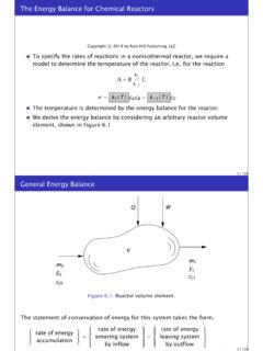
5 System Description A simplified diagram of the reactor vessel and internals is shown in Figure More detailed cutaway and cross-sectional diagrams can be found in Figures , , and , respectively, and are used for the following descriptions. the reactor vessel is cylindrical, with a welded hemispherical bottom head and a removable, flanged and gasketed, hemispherical upper head. The vessel contains the reactor core, core support structures, control rods and other components directly associated with the core. The vessel inlet and outlet nozzles are located in a horizontal plane just below the reactor vessel flange but above the top of the core. Coolant enters the vessel through the inlet nozzles and flows down the core barrel-vessel wall annulus, turns at the bottom and flows up through the core to the outlet nozzles.
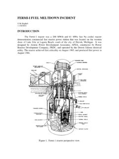
6 the reactor internals are comprised of the upper support structure, the lower core support structure, and the incore instrumentation support structure. They are designed to support, align, and guide the core components, direct the coolant flow to and from the core, and to support and guide the incore instrumentation. The fuel assemblies are arranged in a roughly circular cross-sectional pattern. The fuel is in the form of slightly enriched uranium dioxide ceramic pellets. The pellets are stacked within zircaloy-4 tubular cladding which is plugged and seal welded at the ends to encapsulate the fuel. The fuel rods are internally pressurized with helium during fabrication. Heat generated by the fuel is removed by demineralized light water which flows upward through the fuel assemblies and acts as both moderator and coolant. The fuel assembly loading arrangement for an operating cycle is shown in Figure Refueling is typically accomplished by removing part of the core and replacing it with new fuel.
7 The remaining parts of the core are shuffled. The exact arrangement of the core will depend upon nuclear engineering calculations and vessel embrittlement concerns. For example, to reduce the neutron flux on the vessel, the older fuel can be placed on the outside of the core and the new fuel loaded in the center. Movable neutron absorbing control rods, designated as Rod Cluster Control Assemblies (RCCAs), are provided to accomplish large rapid reactivity additions for USNRC HRTD Rev 0909 reactor control or shutdown purposes. Each RCCA is identical and consists of a number of individual absorber rods attached to a common spider and hub assembly. These absorber rods fit within hollow guide thimbles in the fuel assemblies. As shown in Figure and , the fuel assemblies are positioned and supported vertically in the core between the upper and lower core plates.
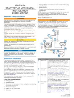
8 These plates are manufactured with pins which fit into holes in the fuel assembly top and bottom nozzles to provide lateral support. The pins maintain the fuel assembly alignment, which ensures free movement of the RCCAs in the fuel assembly without binding or restriction between the rods and their guide surfaces. Component Descriptions Reactor Vessel the reactor vessel is comprised of (1) a flanged cylinder, made of welded rolled plates or ring forgings, welded to a hemispherical bottom and (2) a removable, flanged and gasketed, hemispherical upper head. The vessel is designed to provide the smallest and most economical volume required to contain the core, core support structures, control rods, and flow directing members of the internals packages. The electromechanical control rod drive mechanisms (CRDMs) and incore temperature instrumentation supports are attached to the reactor vessel head.
9 The bottom of the vessel contains penetrations for the incore nuclear instrumentation. All penetrations are welded to their respective head to minimize coolant leakage. Inlet and outlet nozzles are located in a horizontal plane below the reactor vessel flange but above the top of the fuel assemblies. Coolant enters the reactor vessel through the inlet nozzles and flows down the annulus between the vessel wall and the core barrel of the core support structure, then turns at the bottom and flows up through the core to the outlet nozzles. All reactor vessel internals are supported from the internals support ledge, which is machined into the reactor vessel flange. Reactor vessel design parameters are listed in Table Reactor Vessel Construction the reactor vessel and head are constructed of manganese-molybdenum alloy steel, with all surfaces in contact with the reactor coolant clad with weld-deposited stainless steel for corrosion resistance.
10 The method of construction is a number of ring forgings and/or rolled plates welded together to form the large reactor vessel, as shown in Figure Samples of reactor vessel and weld materials are provided to evaluate the effect of radiation on the fracture toughness of the reactor vessel. the reactor vessel surveillance program uses a number of specimen capsules located in irradiation specimen guides (guide baskets) attached to the outside of the neutron shield pads (Figure ). There are two single holders and two double holders. The specimens are positioned at about core midplane height. Dosimeters are also included to evaluate the level of flux experienced by the specimens and vessel wall. USNRC HRTD Rev 0909 The bottom head of the vessel contains 58 penetration nozzles for connection and entry of the incore nuclear instrumentation.