Transcription of What is Simulink?
1 what is simulink ? simulink , an add-on product to MATLAB, provides an interactive, graphical environment for modeling, simulating, and analyzing of dynamic systems. It enables rapid construction of virtual prototypes to explore design concepts at any level of detail with minimal effort. For modeling, simulink provides a graphical user interface (GUI) for building models as block diagrams. It includes a comprehensive library of pre-defined blocks to be used to construct graphical models of systems using drag-and-drop mouse operations. The user is able to produce an up-and-running model that would otherwise require hours to build in the laboratory environment.
2 It supports linear and nonlinear systems, modeled in continuous-time, sampled time, or hybrid of the two. Since students learn efficiently with frequent feedback, the interactive nature of simulink encourages you to try things out, you can change parameters on the fly and immediately see what happens, for what if exploration. Lastly, and not the least, simulink is integrated with MATLAB and data can be easily shared between the programs. In order to use simulink , you must first start MATLAB. With MATLAB running, there are two ways to start simulink : Click the simulink icon on the MATLAB toolbar Type simulink at the MATLAB prompt followed by a carriage return (press the Enter key) 313 In response, MATLAB displays the simulink Library Browser.
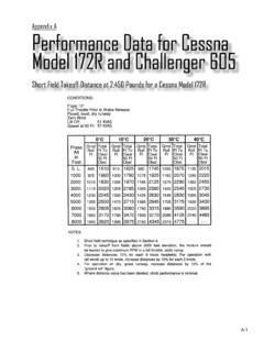
3 314 Next, select New model from the File pull-down menu in the Library Browser. The following blank window appears on your screen. We will refer to this window as the model window. In this model window, models are drawn and edited mainly by mouse driven commands. There are two major categories of elements in simulink : Blocks Lines Blocks are used to generate, modify, combine, output, and display signals. Lines, on the other hand, are used to transfer signals from one block to another. Blocks There are several general classes of blocks, some of which are: Sources: Used to generate various signals. Sources blocks have outputs but no inputs. One may want to use a Constant input, a Sine Wave, a Step, a Ramp, a Pulse Generator, or a Uniform Random number to simulate noise.
4 The Clock may be used to create a time index for plotting purposes. Sinks: Used to output or display signals. Sinks blocks have inputs but no outputs. Examples are Scope, Display, To Workspace, Floating Scope, XY Graph, etc. Discrete: Discrete Filter, Discrete State-Space, Discrete Transfer Fcn, Discrete Zero-Pole, Unit Delay, etc. Continuous: Integrator, State-Space, Transfer Fcn, Zero-Pole, etc. Signal routing: Mux, Demux, Switch, etc. Math Operations: Abs, Gain, Product, Slider Gain, Sign, Sum, etc. 315 Lines Lines transmit signals in the direction indicated by the arrow. Lines must always transmit signals from the output terminal of one block to the input terminal of another block.
5 One exception to this is that a line can tap off of another line. This sends the original signal to two (or more) destination blocks. Lines can never inject a signal into another line; lines must be combined through the use of block such as a summing junction. A signal can be either a scalar signal or a vector signal. - Building a simulink model Building a simulink model of a system consists of selecting the appropriate blocks and connecting them in a way that represents the mathematical models. Since the best way to learn a simulation tool is to work with it, this first tutorial will guide you through a simple example.
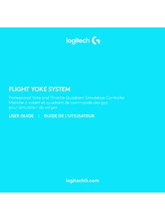
6 We will build the block diagram for a simple model consisting of a sinusoidal input multiplied by a constant gain, which is depicted below. 316 Six Distinct Blocks The simulink model will consist of 6 distinct blocks, namely, Sine Wave, Scope, Mux, Clock, and To Workspace. The Sine Wave is a source block from which a sinusoidal input signal originates. The signal is transferred through a line in the direction indicated by the arrow to the Gain block. The Gain block modifies its input (scales it by 5) and outputs a new signal through a line. The output of the Gain block and the output of the Sine Wave are combined in the multiplexer (Mux) to form a signal vector.
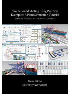
7 The signal vector is transferred through a line to the Scope block used to display a signal much like an oscilloscope. Specifications of model Block Name Specifications Location Sine Wave Amplitude=1v Frequency=1 rad/s Sources Scope Time range=10s Sinks Gain Gain=5 Math Operations 317 Mux 2 Inputs Signal Routing Clock None Sources To Workspace Save Format=Array Sinks simulation Parameters: Stop time=1000; Max step size= model Creation Creating a working model with simulink is straightforward. The process involves four (4) basic steps as depicted in the following flowchart: First you will gather all the necessary blocks from the Library Browser. Then you will modify the blocks so that they correspond to the blocks of the desired model .
8 Lastly, but not the least, you will connect the blocks with lines to form the complete system and set the overall simulation parameters. After this, you will simulate the complete system to verify that it works. 318A. Step one: Select desired blocks Getting the blocks into the model window: Follow the steps below to collect the necessary blocks: Create a new model (New from the File menu). You will get a blank model window Click on the Sources icon in the Library Browser. This opens the Sources window which contains the Sources block library. Sources are used to generate signals. Drag the Sine Wave and Clock blocks from the Sources window into the left side of your model window.
9 Click on the Sinks icon in the Library Browser to open the Sinks window. Drag the Scope and To Workspace blocks into the right side of your model window. Click on the Signal Routing icon in the Library Browser to open the Signal Routing window. Drag the Mux block into the your model window Click on the Math Operations icon in the Library Browser to open Math Operations window. Drag the Gain block into your model window. 319 B. Step 2: Configure block parameters - Resizing and moving blocks: First select the block by clicking with your left mouse button while the pointer is on the block. In each corner of the block a little filled square appears. Put the pointer on one of the corner, press the left mouse button and keep it pressed down.
10 Move the mouse and release the mouse button when the block has the desired size. To move a block you first have to select it. Then put the pointer inside the block, press the left mouse button down and keep it pressed down. Drag the block to its new position and release the mouse button. C. Step 3: Connecting block inputs and outputs- Adding a branch line: To connect the output of the Sine Wave to the input of the Mux block, you will use a branch line. Drawing a branch line is slightly different in that to start, the branch line must be welded to an existing line. Position the pointer on the line that connects the Sine Wave block to the Gain block.