Transcription of WORLD-BEAM QS30 Universal Voltage Instruction …
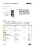
1 Instruction ManualSelf-Contained, Photoelectric Sensors in Universal -Style Housing Advanced one-piece photoelectric sensors with exceptional long-range opticalperformance Compact housing with mounting versatility via its popular 30 mm threaded barrelor side-mount holes 24 V to 250 V ac (50 Hz/60 Hz) and 12 V to 250 V dc operation with SPDT electromechanical relay output Tough ABS/polycarbonate blend housing is rated to IEC IP67, NEMA 6 Easy-to-see sensor status indicators: two status LEDs visible from 360 ; extralarge Output indicator on the back of the sensor housing (except emitters) visiblefrom long distances Opposed, polarized retroreflective, and fixed-field (200 mm, 400 mm, or 600 mmcutoff) models available 2 m integral cable and 152 mm quick-disconnect cable optionsWARNING: Not To Be Used for Personnel ProtectionNever use this device as a sensing device for personnel protection.
2 Doing so could lead toserious injury or death. This device does not include the self-checking redundant circuitry necessaryto allow its use in personnel safety applications. A sensor failure or malfunction can cause either anenergized or de-energized sensor output ModeModelRangeLEDO utput OPPOSED QS303E Emitter60 m (200 ft)Infrared, 875 nmEffective Beam: 18 mm ( in)-QS30VR3R Receiver60 m (200 ft)-SPDT PPOLAR RETRO QS30VR3LP8 m (26 ft)2 Visible red, 630 nm FIXED-FIELD QS30VR3FF200200 mm ( in)Visible red, 680 nmQS30VR3FF400400 mm ( in)QS30VR3FF600600 mm ( in)Fixed-Field Mode OverviewQS30 self-contained fixed-field sensors are small, powerful, infrared diffuse mode sensors with far-limit cutoff (a type ofbackground suppression). Their high excess gain and fixed-field technology allow detection of objects of low reflectivity,while ignoring background cutoff distance is fixed.
3 Backgrounds and background objects must always be placed beyond the cutoff 2 m ( ft) cable models are listed. For 9 m (30 ft) integral cable: add suffix "W/30 (for example, QS303E W/30). 5-pin Micro-style 152 mm (6 in) cable: add "QPMA" (for example, QS303 EQPMA).2 Range is measured using a model BRT-84 QS30 Universal Voltage Original Document119166 Rev. D15 December 2016119166 Fixed-Field Sensing Theory of OperationThe QS30FF compares the reflections of its emitted light beam (E) from an object back to the sensor's two differentlyaimed detectors, R1 and R2. See Figure 1 on page 2. If the near detector's (R1) light signal is stronger than the fardetector's (R2) light signal (see object A in the Figure below, closer than the cutoff distance), the sensor responds to theobject. If the far detector's (R2) light signal is stronger than the near detector's (R1) light signal (see object B in theFigure below, beyond the cutoff distance), the sensor ignores the cutoff distance for model QS30FF sensors is fixed at 200, 400 or 600 millimeters (8 in, 16 in, or 24 in).
4 Objects lyingbeyond the cutoff distance are usually ignored, even if they are highly reflective. However, under certain conditions, it ispossible to falsely detect a background object (see Background Reflectivity and Placement on page 2).R1R2 LensesObjectAObject BorBackgroundSensingRangeCutoffDistanceE ReceiverElementsNearDetectorFarDetectorE mitterObject is sensed if amount of light at R1 is greater than the amount of light at R2 Figure 1. Fixed-Field ConceptSensingAxisR1R2 EFigure 2. Fixed-Field Sensing AxisIn the drawings and information provided in this document, the letters E, R1, and R2 identify how the sensor's threeoptical elements (Emitter "E", Near Detector "R1", and Far Detector "R2") line up across the face of the sensor. Thelocation of these elements defines the sensing axis, see Figure 2 on page 2.
5 The sensing axis becomes important in certainsituations, such as those illustrated in Figure 5 on page 3 and Figure 6 on page SetupSensing ReliabilityFor highest sensitivity, position the target for sensing at or near the point of maximum excess gain. See PerformanceCurves section for excess gain curves. Sensing at or near this distance makes the maximum use of each sensor s availablesensing power. The background must be placed beyond the cutoff distance. Note that the reflectivity of the backgroundsurface also may affect the cutoff distance. Following these guidelines improves sensing Reflectivity and PlacementAvoid mirror-like backgrounds that produce specular reflections. A false sensor response occurs if a background surfacereflects the sensor's light more to the near detector (R1) than to the far detector (R2).
6 The result is a false ON condition(Figure 3 on page 3). Correct this problem by using a diffusely reflective (matte) background, or angling either thesensor or the background (in any plane) so the background does not reflect light back to the sensor (Figure 4 on page3). Position the background as far beyond the cutoff distance as object beyond the cutoff distance, either stationary (and when positioned as shown in Figure 5 on page 3), ormoving past the face of the sensor in a direction perpendicular to the sensing axis, may cause unwanted triggering of thesensor if more light is reflected to the near detector than to the far detector. Correct the problem by rotating the sensor90 (Figure 6 on page 3). The object then reflects the R1 and R2 fields equally, resulting in no false triggering.
7 A bettersolution, if possible, may be to reposition the object or the sensor. WORLD-BEAM QS30 Universal - Tel: +1-763-544-3164P/N 119166 Rev. DFixed SensingFieldCutoffDistanceR1 = Near Detector R2 = Far Detector E = EmitterQS30 FFR1R2 EReflective Background or Moving ObjectFigure 3. Reflective Background - ProblemFixed SensingFieldE = EmitterR2 = Far DetectorR1 = Near DetectorQS30 FFCutoff DistanceE, R2, R1 Reflective Background or Moving ObjectFigure 4. Reflective Background - SolutionQS30 FFR1 = Near DetectorR2 = Far Detector E = EmitterCore ofEmittedBeamCutoffDistanceReflectiveBac kgroundStrongDirectReflectionto R1 Fixed SensingFieldR1R2EA reflective background object in this position or moving across thesensor face in this axis and direction may cause a false 5.
8 Object Beyond Cutoff - ProblemQS30 FFR1R2ER1 = Near DetectorR2 = Far Detector E = EmitterCore ofEmittedBeamReflectiveBackgroundFixed SensingFieldStrongDirectReflectionAway From SensorCutoffDistanceA reflective background object in this position or moving across thesensor face in this axis is 6. Object Beyond Cutoff - SolutionColor SensitivityThe effects of object reflectivity on cutoff distance, though small, may be important for some applications. It is expectedthat at any given cutoff setting, the actual cutoff distance for lower reflectance targets is slightly shorter than for higherreflectance targets. This behavior is known as color example, an excess gain of 1 for an object that reflects 1/10 as much light as the 90% white card is represented bythe horizontal graph line at excess gain = 10.
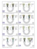
9 An object of this reflectivity results in a far limit cutoff of approximately 190mm ( in) for the 200 mm (8 in) cutoff model, for example; and 190 mm represents the cutoff for this sensor excess gain curves were generated using a white test card of 90% reflectance. Objects with reflectivity of less than90% reflect less light back to the sensor, and thus require proportionately more excess gain in order to be sensed with thesame reliability as more reflective objects. When sensing an object of very low reflectivity, it may be especially importantto sense it at or near the distance of maximum excess DiagramsCabled Emitters bnbu24 - 250V ac (50/60 Hz)12 - 250V dc Other Cabled ModelsCable and QPMA hookups are functionally identical. - 250V ac (50/60 Hz)12 - 250V dc WORLD-BEAM QS30 Universal Voltage P/N 119166 Rev.
10 - Tel: +1-763-544-31643 SpecificationsSupply VoltageUniversal Voltage : 24 V to 250 V ac (50 Hz/60 Hz) or 12 V to 250 Vdc ( watt maximum)Supply Protection CircuitryProtected against transient voltagesOutput ConfigurationSPDT (Single-Pole Double-Throw) electromechanical relay output (allmodels except emitters)Output RatingMax. Switching Power (resistive load): 150 W, 1250 VAMax. Switching Voltage (resistive load): 250 V ac; 125 V dcMax. Switching Current (resistive load): 5 A at 250 V ac; 5 A at 30V dc derated to 200 mA at 125 V dcMin. Voltage and Current: 5 V dc, 10 mAMechanical life of relay: 50 million operationsElectrical life of relay at full resistive load: 100,000 operationsOutput Response15 milliseconds ON and OFFNOTE: 100 millisecond delay on power-up;output does not conduct during this Point ToleranceFixed-Field Only: 5% of nominal cutoff distanceIndicatorsTwo LEDs (Green and Amber) on top of sensorGreen ON: power to sensors is ONAmber ON: light sensedAmber flashing: excess gain marginal (1 to times) in lightconditionLarge, oval LED indicator on sensor back (except emitters)Amber ON: normally open output is conductingConstructionABS housing, rated IEC IP67, NEMA 6.