Transcription of www.metraonline.com
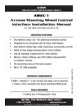
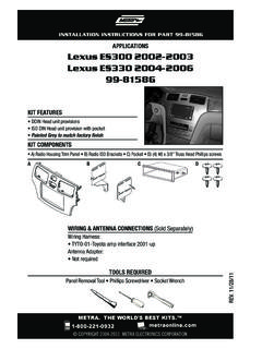
1 CAUTION! All accessories, switches, climate controls panels , and especially air bag indicator lights must be connected before cycling the ignition. Also, do not remove the factory radio with the key in the on position, or while the vehicle is running. The World s Best Kits. COPYRIGHT 2018 METRA ELECTRONICS CORPORATION REV. 10/22/18 INST99-6514 BINSTALLATION INSTRUCTIONS99-6514 BKIT FEATURES ISO DIN radio provision with pocket ISO DDIN radio provision Included interface retains factory screen Painted matte black to match factory finishNote: Does not retain sound from Driver Convenience Group KIT COMPONENTS A) Radio trim panel B) Radio brackets C) Pocket D) (4) #8 x 3/8 Phillips screws E) (2) Plastic panel clips F) (2) Metal panel clips Axxess interface and harness (not shown)TOOLS REQUIRED Panel removal tool Phillips screwdriver T-30 Torx screwdriverTABLE OF CONTENTSDash Disassembly.
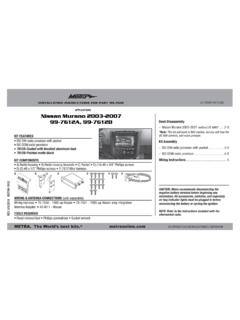
2 2 Kit Assembly ISO DIN radio provision with pocket ..3 ISO DDIN radio provision ..3 Axxess Interface Installation ..4-8 WIRING & ANTENNA CONNECTIONSW iring Harness: Interface and harness includedAntenna Adapter: 40-EU10*Steering wheel control interface: ASWC-1*Backup camera retention: AX-CHRYCAM-1** Sold separatelyABCDEFD odge Charger | DISASSEMBLY1. For vehicles with an 8 speed transmission: Unclip and remove the top of the shift knob assembly. Next, remove the (1) exposed T-30 Torx screw from the shift knob and then pull up on the knob to remove. (Figure A) For vehicles without an 8 Speed transmission: Push the collar down at the base of the shift knob and remove the pin then pull up on shift knob to remove.
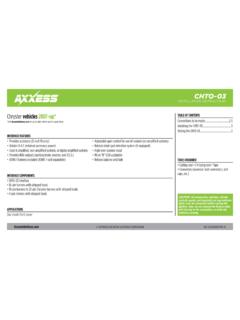
3 (Figure B)(Figure A)(Figure D)(Figure B)(Figure E)(Figure F)(Figure C)2. Unclip and remove the shifter trim panel. (Figure C)3. Remove (2) Phillips screws securing the pocket below the climate controls then unclip and remove the pocket. (Figure D)4. Unclip, unplug, and remove the factory radio/climate control panel. (Figure E)5. Remove (4) Phillips screws securing the radio chassis, and then unplug and remove the chassis. (Figure F) Continue to Kit AssemblyREV. 10/22/2018 INST99-6514B3 KIT ASSEMBLY(Figure A)(Figure B)(Figure C)ISO DIN radio provision with pocket1. Attach the provided clips to the radio trim panel (metal clips at top and plastic at the bottom).
4 (Figure A)2. Secure the pocket to the radio brackets with the (4) #8 x 3/8 Phillips pan head screws supplied. (Figure B)3. Remove the metal DIN sleeve and trim ring from the aftermarket radio. 4. Slide the radio into radio brackets and secure with the screws supplied with the radio. (Figure C) Continue to Axxess Interface InstallationISO DDIN radio provision1. Attach the provided clips to the radio trim panel (metal clips at top and plastic at the bottom). (Figure A)2. Secure the radio to the radio brackets using the screws supplied with the radio. (Figure B) Continue to Axxess Interface Installation(Figure A)(Figure B) | INTERFACE INSTALLATION Provides accessory power (12-volt 10-amp) Retains (retained accessory power) Used in amplified or non-amplified systems Provides NAV outputs (parking brake, reverse, and speed sense) Prewired ASWC-1 harness (ASWC-1 sold separately) Retains balance and fade Ability to add an aftermarket backup camera or additional video input Retains the factory display screen Micro B USB updatableNote: Does not retain sound from Driver Convenience Group Connections.
5 5 Installation ..6 Programming ..6 Final assembly ..6 Audio level adjustment ..6 Screen operation ..6 Video option screen ..7 Updating ..8 INTERFACE FEATURESTABLE OF CONTENTS Crimping tool and connectors, or solder gun, solder, and heat shrink Tape Wire cutter Zip ties Small flat-blade screwdriverTOOLS REQUIRED Axxess interface 16-pin harness with stripped leads 6514 harnessINTERFACE COMPONENTSREV. 10/22/2018 INST99-6514B5 From the 16-pin harness with stripped leads to the aftermarket radio: Connect the Red wire to the accessory wire. Note: If also installing an ASWC-1 (sold separately), there will be a Red wire on the 6514 harness to connect as well.
6 Connect the Orange/White wire to the illumination wire, if applicable. If the vehicles equipped with a factory amplifier, connect the Blue/White wire to the amp turn-on following (3) wires are for aftermarket multimedia/navigation radios that require these wires: Connect the Light Green wire to the parking brake wire. Connect the Blue/Pink wire to the VSS or speed sense wire. Connect the Green/Purple wire to the reverse wire. Tape off and disregard the following (9) wires, they will not be used in this application: Brown, White, White/Black, Gray, Gray/Black, Purple, Purple/Black, Green, Green/BlackFrom the 6514 harness to the aftermarket radio: Connect the Black wire to the ground wire.
7 Connect the Yellow wire to the battery wire. Connect the Gray wire to the right front positive speaker output Connect the Gray/Black wire to the right front negative speaker output Connect the White wire to the left front positive speaker output Connect the White/Black wire to the left front negative speaker output Connect the Green wire to the left rear positive speaker output. Connect the Green/Black wire to the left rear negative speaker output. Connect the Purple wire to the right rear positive speaker output. Connect the Purple/Black wire to the right rear negative speaker output.
8 Tape off and disregard the following (4) wires, they will not be used in this application: Purple, Purple/Black, Green, Green/Black Disregard the Yellow RCA jack labeled (1), it will not be used in this application. Connect the Yellow RCA jack labeled (2) to either an aftermarket backup camera, or an AUX video input. Connect the Red & White RCA jacks to the audio AUX-IN pre-wired ASWC-1 harness: The 12-pin harness is to be used along with the optional ASWC-1 (sold separately) to retain steering wheel controls. If the ASWC-1 is not being used, disregard this harness. If it will be used, please refer to the ASWC-1 instructions for programming.
9 Disregard the harness that comes with the TO BE | OPERATIONFINAL ASSEMBLYA ttention! For models with a 8-inch screen, update the interface via the Axxess Updater available at Select 8-inch screen once prompted to. Instructions to update the interface are available at the end of this instruction the key in the off position: 1. Connect the 16-pin harness with stripped leads, and the 6520 harness, into the interface. 2. Connect the factory White 4-pin harness removed in step 5 of Dash Disassembly to the Black connector from the interface. Note: The display screen will not function without this connection.
10 3. Connect the 6514 harness to the wiring harness in the vehicle. 4. Connect the climate control harness from the vehicle to the 99-6514B radio trim panel. This is the harness that was removed in step 4 of dash disassembly. 5. Locate the factory antenna connector in the dash and complete all necessary connections to the radio. Metra recommends using the proper mating adapter from Metra. Note: If an ASWC-1 (sold separately) will be used, do not connect it until the interface is programmed and fully functional. 1. Secure the completed radio assembly to the dash using the factory hardware. 2. Reassemble the dash in reverse order of disassembly using the 99-6514B panel.