Transcription of www.metraonline.com
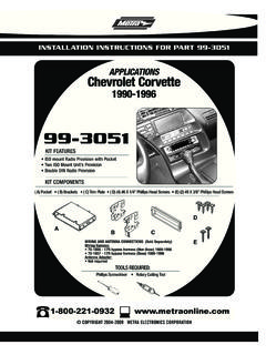
1 99-9714. I N S TA L L AT I O N I N S T R U C T I O N S. harley - davidson Street Glide, electra Glide, TABLE OF CONTENTS. Fairing Disassembly Ultra and Limited models 2014-up* / Road harley davidson Street Glide, electra Glide, Ultra, and Limited models Glide 2015-up* harley davidson Road Glide *Visit for up-to-date vehicle specific applications. Kit KIT FEATURES Axxess interface 6-13. ISO DIN radio provision Included interface and LCD info screen WIRING & ANTENNA CONNECTIONS (sold separately). ASWC-1 included, for retention of handlebar controls Wiring Harness: Axxess interface and harness included 44-UA20 antenna included Antenna Adapter: 44-UA20 included KIT COMPONENTS Steering wheel control interface: Included A) Radio housing B) Radio brackets C) LCD screen D) LCD back plate E) (10) #8 x 3/8 Phillips screws Axxess interface (not shown). TOOLS REQUIRED. A B C D. Panel removal tool Phillips screwdriver Torx screwdrivers Allen wrenches CAUTION!
2 All accessories, switches, climate controls panels, and especially air bag indicator lights must be connected before cycling the ignition. Also, do not remove the factory radio E with the key in the on position, or while the vehicle is running. The World's best kits. COPYRIGHT 2017 METRA ELECTRONICS CORPORATION REV. 6/20/17 INST99-9714. DASH DISASSEMBLY. harley davidson Street Glide, electra Glide, Ultra, and Limited models 2014-up 1. Remove (4) T-27 from inner fairing. (Figure A). 2. Remove (3) T-27 from windshield (caution not to drop the outer fairing or windshield). (Figure B). 3. Remove outer fairing, unplugging the headlight. (Figure C). 4. Remove (2) T-27 to remove the fairing (Figure A) (Figure C). vent and remove the vent. (Figure D). Continued on next page (Figure B) (Figure D). 2 | DASH DISASSEMBLY (CONT). 5. Remove (11) screws securing the radio bracket: (Figure E). a. (2) T-27 Torx screws shared with the gauge cluster and a third T-27 Torx screw to remove the gauge cluster in step 7.
3 B. (4) 5/32 Allen screws facing outward. c. (4) T-25 Torx screws secured to the radio. d. (1) T-25 Torx screw shared with the storage pocket. 6. Remove the radio bracket. (Figure E). Note: This bracket will be reused with (Figure E). the 99-9714 kit. 7. Remove the gauge cluster. (Figure E). 8. Remove (4) 3/16 Allen screws from the sides of radio. (Figure F). Note: These screws will be reused with the 9714 kit. 9. Slide the radio out toward the rear of the (Figure F). bike, and unplug the radio. (Figure F). REV. 6/20/2017 INST99-9714 3. DASH DISASSEMBLY (CONT). harley Road Glide 2015-up 1. Remove the lower torx screws on 7. Remove the fairing and set aside. either side holding the wind deflector 8. Remove (4) 3/16 Allen screws from the wings (only the lower two need to be sides of the radio. removed). (Figure A). Note: These screws will be reused with 2. Remove (1) 3/16 Allen screw securing the 9714 kit.
4 Each turn signal. (Figure B) (Figure A) (Figure D). CAUTION: Be sure to hold the radio when 3. Remove (4) Phillips screws from the removing the last screw so it will not drop. windshield and set the windshield aside. (Figure C) 9. Unplug and remove the radio. 4. Remove the top fairing trim clipped to 10. Remove (2) Torx screws securing the the top of the radio. (Figure D) fairing bracket attached to the radio. 5. Unplug the turn signals. Note: This bracket will be reused (Figure B) with the 99-9714 kit. Please note the (Figure E). 6. Remove the speaker grills with a panel orientation of the bracket. The curved removal tool and remove (1) torx screw portion faces the rear of the bike. from each side.(Figure E). CAUTION: The fairing will be loose at this point. Have a helper hold it to keep from damaging it when removing the screws. (Figure C). 4 | KIT ASSEMBLY. ISO DIN radio provision 6. a. For the Street Glide, electra Glide, 1.
5 Secure the radio brackets to the radio Ultra, and Limited models 2014-up: housing with (4) #8 x 3/8 Phillips Attach the radio bracket removed screws supplied. (Figure A) in step 6 of disassembly to the top of the radio housing assembly, 2. Remove the metal DIN sleeve and trim and secure with (4) Phillips screws ring from the aftermarket radio. supplied. 3. Slide the radio into the radio housing b. For the Road Glide 2015-up: assembly and secure with screws Attach the fairing bracket removed supplied with the radio. (Figure B) in step 10 of disassembly to the 4. Insert the LCD screen into the radio top of the radio housing assembly, (Figure C). (Figure A). housing, route the cable through the and secure with (2) Phillips screws LCD back plate, and then secure to the supplied. Ensure the bracket is far radio housing assembly using (2) #8 forward, and the curved portion x 3/8 screws supplied with the kit.
6 Is facing the rear of the bike as (Figure C) mentioned in disassembly. 5. Secure the radio housing assembly to Continue to Axxess Interface Installation the bike using (4) 3/16 Allen screws previously removed in step 8 of disassembly. (Figure D). (Figure B) (Figure D). REV. 6/20/2017 INST99-9714 5. AXXESS INTERFACE INSTALLATION. INTERFACE FEATURES TABLE OF CONTENTS. Provides accessory power (12-volt 10-amp) Wiring High level speaker input Installing the Retains balance and fade Initializing the Retains oil pressure and EITMS status Handlebar Control 10-13. ASWC-1 included, for retention of handlebar controls Updating the 14. Micro B USB updatable INTERFACE COMPONENTS TOOLS REQUIRED. Axxess interface Cutting tool Crimping tool Tape 99-9714 harness Connectors (example: butt-connectors, bell caps, etc.). ASWC-1 Interface Female connector with Brown and Brown/White wires 6 | WIRING INSTRUCTIONS. From the 99-9714 harness to the aftermarket radio: Eclipse: Connect the steering wheel control wire, normally Brown, to the Brown/White Connect the Black wire to the ground wire.
7 Wire of the connector. Then connect the remaining steering wheel control wire, normally Brown/White, to the Brown wire of the connector. Connect the Yellow wire to the battery wire. Metra OE: Connect the steering wheel control Key 1 wire (Gray) to the Brown wire. Connect the Red wire to the accessory wire. Kenwood or select JVC with a steering wheel control wire: Connect the Blue/Yellow wire Connect the Orange wire to the illumination wire. (If the aftermarket radio has no illumination to the Brown wire. wire, tape off the Orange wire). Note: If your Kenwood radio auto detects as a JVC, manually set the radio type to Connect the White wire to t he left front positive speaker output. Kenwood. See the instructions under changing radio type. Connect the White/Black wire to the left front negative speaker output. XITE: Connect the steering wheel control SWC-2 wire from the radio to the Brown wire. Connect the Gray wire to the right front positive speaker output.
8 Parrot Asteroid Smart or Tablet: Connect the jack into the AX-SWC-PARROT (sold Connect the Gray/Black wire to the right front negative speaker output. separately), and then connect the 4-pin connector from the AX-SWC-PARROT into the radio. Connect the Green wire to the left rear positive speaker output. Note: The radio must be updated to rev. or higher software. Connect the Green/Black wire to the left rear negative speaker output. Universal 2 or 3 wire radio: Connect the steering wheel control wire, referred to as Key-A or SWC-1, to the Brown wire of the connector. Then connect the remaining steering Connect the Purple wire to the right rear positive speaker output. wheel control wire, referred to as Key-B or SWC-2, to the Brown/White wire of the Connect the Purple/Black wire to the right rear negative output connector. If the radio comes with a third wire for ground, disregard this wire. Note: After the interface has been programmed to the vehicle, refer to the manual 12-pin pre-wired ASWC-1 harness: provided with the radio for assigning the SWC buttons.
9 Contact the radio manufacturer for This harness is to be used along with the ASWC-1 (provided) to retain handlebar audio more information. controls. Please note that handlebar control is also referred to as steering wheel control . For all other radios: Connect the jack into the jack on the aftermarket radio For the radios listed below, connect the included female connector with stripped designated for an external steering wheel control interface. Please refer to the aftermarket leads, to the male SWC jack. Any remaining wires tape off and disregard: radios manual if in doubt as to where the jack goes to. REV. 6/20/2017 INST99-9714 7. INSTALLING THE INTERFACE INITIALIZING THE INTERFACE. It is highly advisable to read the following steps beforehand, to ensure a clear understanding of Attention! If the interface loses power for any reason, the following steps will need to be what is to be expected. The following steps must be done in the order that they are numbered.
10 Performed again. With the key in the off position: 1. Turn the key to the ignition position and wait until the radio comes on. 1. Connect the 99-9714 harness into the interface, and then to the wiring harness in the Note: If the radio does not come on within 60 seconds, turn the key to the off position, disconnect the vehicle. interface, check all connections, reconnect the interface, and then try again. 2. Connect the LCD screen into the interface. 2. Program the LCD screen: a. Pull the screen protector from the LCD screen. 3. Connect the 44-UA20 (provided), and complete all necessary connections to the radio. Metra recommends using the proper mating adapter from Metra. b. Press and hold the Return/ESC button on the LCD screen for 5 seconds until Select Interface . comes up. 4. Do not connect the ASWC-1 just yet, leave it disconnected. c. Select Connection Type , and then press Enter . Attention! To prevent error codes, all electronic devices including the headlight and turn d.
