Transcription of www.passivecomponent
1 Of ContentsVaristors-5D Series .. 3 Varistors-7D Series .. 4 Varistors-10D Series .. 5 Varistors-14D Series .. 6 Varistors-20D Series .. 7 Varistors-25D Series .. 8 Varistors-5E 7E Series .. 9 Varistors-10E 14E Series .. 10 Varistors-18E 20E Series ..11V-I Curve .. 12 Packing Specification (5 - 25 Series) .. 15 Taping Specifications - 5 and 7 .. 16 Taping Specifications - 10 and 14 .. 17 Taping Specifications - 18 and 20 .. 18 Big Size Varistor - 32D Series .. 19 Big Size Varistor - 34mm Single Series .. 20 Big Size Varistor - 34mm Dual Series .. 21 Big Size Varistor - 40D Series .. 22 Big Size Varistor - 53D Series .. 23 Packing of Big MOV and Soldering of MOV .. 25 Multilayer Chip Varistor(MLV) .. 26 Subject PageSubject PageINDEX* The specifications are subject to change or our products in it may be discontinued without advance notice. Please check with our sales representatives or product engineers before ordering.* This catalog has only typical specifications because there is no space for detailed specifications.
2 Therefore, please approve our product specifications or transact the approval sheet for product specification before ordering. HOW TO ORDERSR241K10DS40 CXType CodeSR: Walsin Varistor Varistor Voltage (DC volt) (From 180 to 112) Two significant digits Followed by no. of zeros 180=18volt 101=100volt 102=1000volt ToleranceJ: 5% K: 10% Disk Size Code05:5mm07:7mm10:10mm14:14mm18:18mm20: 20mm25:25mmDisk typeD: Standard disk typeE: High energy disk type Lead Type or Taping CodeS : Straight Lead L : Inline Crimped O: Outward CrimpedI : Inward Crimped Taping Code (Please see below) Lead CuttingLead Cutting for Bulk Packing: A0=10 B0=19mm minC0=29mm min D0=39mm minE0=49mm minF0=10mm min H0=30mm min G0=20mm minL0=50mm min I0=40mm minA5=15 G5=25mm minCoating-P=Phenoliccoating -B=Phenolic coating -S=Silicone coating-F=HF Epoxy coating-Y=Without coating-T=Epoxy coatingSpacial Request Special lead cutting tolerance Special lead spacing (Please see below) Special varistor voltage * I f customers have no special request on lead shape, we provide straight lead for voltage type 471K and in-line crimped lead for voltage type 511K.
3 VARISTOR SPECIAL REQUEST lead length tolerance for short lead cutting (exclude straightlead) lead spacing for 20D and 20E (lead wire is diameter) Z:5mm lead spacing for 10D(E), 14D(E) H:Special request DIMENSIONS QUICK REFERENCE :If specific item s dimensions, please contact salesSeries5D,5E7D,7E10D,10E14D,14E18E20 D, 9. d* W** * ** (Unit: mm)Metal Oxide Varistor(MOV)Metal Oxide Varistor(MOV) VARISTOR PART NUMBER EXAMPLES SR241K07DT14: 7mm, 241K, inward crimped lead and reel taped. SR361K10DI45: 10mm, 361K, bulk packing, inward crimped lead,lead cutting length SR621K20 EOP2: 20mm, 621K, high energy, bulk, outward crimped lead, lead spacing 12mm SR271K20DO65X: 20mm, 271K, bulk, outward crimped lead, lead spacing mm, lead cutting SR241K10DS40F: 10mm, 241K, bulk, straight lead, lead Remark: The lead length (L) is 20mmminimum unless requested by customers; please refer to leadcutting code in How to Order.
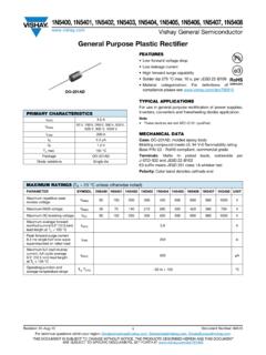
4 CHARACTERISTICS High performance transient voltage suppression Short response time to surge voltage Low standby power dissipation Excellent clamping characteristics High performance withstanding surge currents High reliability UL, CSA, VDE and CQC recognized DEFINITION OF VARISTOR TERMSR ated RMS Voltage, Rated DC Voltage :The maximum designated values of power system voltagethat may be applied continuously between the terminals of a device. Varistor Voltage :Test characteristic that is used to classify varistors by test current of 1mA DC is typically used to determinevaristor voltage classification type. Varistor voltage clamping characteristics can be defined at various test Peak Single Pulse Transient Current :Maximum surge current, 8/20 s waveform which a varistor israted to withstand for a single Single Pulse Transient Energy :Maximum allowable energy for a single impulse (see specifiedwaveforms).
5 Maximum Clamping Voltage : Measured peak voltage across the device terminals whena current impulse of specified amplitude and waveform isconducted through the Capacitance :Typical capacitance values are measured at a test frequencyof 1kHz. Capacitance values are only for reference purpose only, not subject to outgoing inspection. ENERGY DERATING VERSUS TEMPERATUREM etal Oxide Varistor(MOV)Metal Oxide Varistor(MOV) APPLICATIONS Surge protection in: Consumer electronics Industrial electronics Communication electronics Measuring and controlling systems Electronic home appliances Protection against surges induced by lighting striking incoming power lines. Suppression of surges caused by switching inductive loads suchas transformers, relays and coils. Protection of rectification diodes, SCRs, power transistors, semiconductor devices, etc GENERAL CHARACTERISTICS Storage Temperature : 55 C to +125 COperating Surface Temperature : 125 COperating Ambient Temperature : 55 C to +85 C (without derating)Maximum Voltage-Temperature Coefficient : < / CInsulation Resistance : 1000 Mega-ohm minimumHi Pot (Leads To Case, 1 Min.)
6 : 2500 VDCT ypical Response Time : <15 Nero-secondsEpoxy Rating : 94V-0 Current / Energy Derating (>85 C ) : / CDC Leakage Current : 200 A maximum (at rated DC working voltage )Solderability : MIL-STD-202 FPower Dissipation Ratings(P, in-watts) :Disc Size 11 Vac~40 Vac 50 Vac~680 Vac 5mm -- -- -- (single) -- (dual) -- -- -- definitions are according to IEEE specifications PEAK CURRENT PER PULSE VERSUS PULSE DURATION Surge protection in: derating)voltage )All definitions are according to IEEE specifications ofPulses on OrderFrom 100 %Respectively capacitance values are measured at a test frequency50 Vac~680 VacDisc Size11 Vac~ ).Maximum Clamping Voltage :Measured peak voltage across the device terminals whena current impulse of specified amplitude and waveform isconducted through the Capacitance :rated to withstand for a single Single Pulse Transient Energy :Maximum allowable energy for a single impulse (see specifiedTypical Response Time : <15 Nero-secondsvaristor voltage classification type.
7 Varistor voltage clampingcharacteristics can be defined at various test Peak Single Pulse Transient Current :Maximum surge current, 8/20 s waveform which a varistor isSolderability : MIL-STD-202 FPower Dissipation Ratings(P, in-watts) :Epoxy Rating : 94V-0 Current / Energy Derating (>85 C ) : / CDC Leakage Current : 200 A maximum (at rated DC workingOperating Surface Temperature : 125 CInsulation Resistance : 1000 Mega-ohm minimumHi Pot (Leads To Case, 1 Min.) : 2500 VDCTest characteristic that is used to classify varistors by test current of 1mA DC is typically used to determine APPLICATIONSLow standby power dissipationIndustrial electronicsCommunication electronicsProtection of rectification diodes, SCRs, power transistors,semiconductor devices, etcExcellent clamping characteristicsHigh performance withstanding surge currentsHigh reliabilityUL, CSA, VDE and CQC recognized High performance transient voltage suppressionThe maximum designated values of power system voltagethat may be applied continuously between the terminals of a Voltage :Suppression of surges caused by switching inductive loads suchas transformers, relays and Ambient Temperature : 55 C to +85 C (withoutMaximum Voltage-Temperature Coefficient : < / CConsumer electronics DEFINITION OF VARISTOR TERMS GENERAL CHARACTERISTICSR ated RMS Voltage, Rated DC Voltage :Storage Temperature.))
8 55 C to +125 CShort response time to surge voltageMeasuring and controlling systemsElectronic home appliancesProtection against surges induced by lighting striking incomingpower (single) 1kHz. Capacitance values are only for reference purposeonly, not subject to outgoing (dual) ENERGY DERATING VERSUS TEMPERATURE PEAK CURRENT PER PULSE VERSUS PULSE106 Pulses1 Pulses10 Pulses102 Pulses103 Pulses104 Pulses105 HOW TO ORDERSR241K10DS40 CXType CodeSR: Walsin Varistor Varistor Voltage (DC volt) (From 180 to 112) Two significant digits Followed by no. of zeros 180=18volt 101=100volt 102=1000volt ToleranceJ: 5% K: 10% Disk Size Code05:5mm07:7mm10:10mm14:14mm18:18mm20: 20mm25:25mmDisk typeD: Standard disk typeE: High energy disk type Lead Type or Taping CodeS : Straight Lead L : Inline Crimped O: Outward CrimpedI : Inward Crimped Taping Code (Please see below) Lead CuttingLead Cutting for Bulk Packing: A0=10 B0=19mm minC0=29mm min D0=39mm minE0=49mm minF0=10mm min H0=30mm min G0=20mm minL0=50mm min I0=40mm minA5=15 G5=25mm minCoating-P=Phenoliccoating -B=Phenolic coating -S=Silicone coating-F=HF Epoxy coating-Y=Without coating-T=Epoxy coatingSpacial Request Special lead cutting tolerance Special lead spacing (Please see below) Special varistor voltage * I f customers have no special request on lead shape, we provide straight lead for voltage type 471K and in-line crimped lead for voltage type 511K.
9 VARISTOR SPECIAL REQUEST lead length tolerance for short lead cutting (exclude straightlead) lead spacing for 20D and 20E (lead wire is diameter) Z:5mm lead spacing for 10D(E), 14D(E) H:Special request DIMENSIONS QUICK REFERENCE :If specific item s dimensions, please contact salesSeries5D,5E7D,7E10D,10E14D,14E18E20 D, 9. d* W** * ** (Unit: mm)Metal Oxide Varistor(MOV)Metal Oxide Varistor(MOV) VARISTOR PART NUMBER EXAMPLES SR241K07DT14: 7mm, 241K, inward crimped lead and reel taped. SR361K10DI45: 10mm, 361K, bulk packing, inward crimped lead,lead cutting length SR621K20 EOP2: 20mm, 621K, high energy, bulk, outward crimped lead, lead spacing 12mm SR271K20DO65X: 20mm, 271K, bulk, outward crimped lead, lead spacing mm, lead cutting SR241K10DS40F: 10mm, 241K, bulk, straight lead, lead Remark: The lead length (L) is 20mmminimum unless requested by customers; please refer to leadcutting code in How to Order.
10 CHARACTERISTICS High performance transient voltage suppression Short response time to surge voltage Low standby power dissipation Excellent clamping characteristics High performance withstanding surge currents High reliability UL, CSA, VDE and CQC recognized DEFINITION OF VARISTOR TERMSR ated RMS Voltage, Rated DC Voltage :The maximum designated values of power system voltagethat may be applied continuously between the terminals of a device. Varistor Voltage :Test characteristic that is used to classify varistors by test current of 1mA DC is typically used to determinevaristor voltage classification type. Varistor voltage clamping characteristics can be defined at various test Peak Single Pulse Transient Current :Maximum surge current, 8/20 s waveform which a varistor israted to withstand for a single Single Pulse Transient Energy :Maximum allowable energy for a single impulse (see specifiedwaveforms).