Example: confidence
XPDR/DME TCAS/ADS-B/TIS/UAT TEST SET
SAFETY SYMBOLS IN MANUALS AND ON UNITS CAUTION: Refer to accompanying documents. (This symbol refers to ... 4.6.3 TIS-B GEN 1-2-4 107 4.6.4 TIS-B GEN Data 1-2-4 109 4.6.5 ADS-B GEN 1-2-4 109 ... Recommended Test Locations 1 …
Tags:
Information
Domain:
Source:
Link to this page:
Documents from same domain
MAP Variable Optical Attenuator - viavisolutions.com
www.viavisolutions.com3 MAP Variable Optical Attenuator Specifications Parameter Single-Mode Multimode Standard With Output Power Monitor Standard With Output Power Monitor

VIAVI Solutions Data Sheet VIAVI
www.viavisolutions.comVIAVI Solutions Data Sheet VIAVI CellAdvisor™ JD785B Base Station Analyzer Spectrum Analyzer: 9 kHz to 8 GHz Cable and Antenna Analyzer: 5 MHz to 6 GHz
Cable Network Maintenance and Service Test Guide
www.viavisolutions.comThe following is a short list of cable network maintenance and service use cases. 2 Cable Subscriber Installation & Test Guide Use Case 1. Node Activation Performance Verification, Alignment, Troubleshooting Problem: As nodes are activated, the fiber connection must be tested with a power meter to verify that proper
Test and Measurement Solutions - viavisolutions.com
www.viavisolutions.comsolutions for line sweep measurement, RF / optical power measurements, and fiber inspection, all in a lightweight, cloud-enabled instrument ideal for cell site installation. Application
VIAVI Solutions Data Sheet VIAVI
www.viavisolutions.comSmartOTDR Handheld Fiber Tester ... Pulse widths 5 ns to 20 µs 5 ns to 20 µs 3 ns to 20 µs Event dead zone4 1.35 m 1.35 m 0.9 m Attenuation dead zone5 4 m 4 m 2.5 m Splitter attenuation dead zone Not available Not available 45 m after 15 dB splitter loss CW Light Source9

G.709 – The Optical Transport Network (OTN)
www.viavisolutions.comto DWDM optical networks. The OTN is specified in the International Telecommunications Union (ITU-T) G.709 Network Node Interface for the OTN. This recommendation, sometimes referred to as digital wrapper (DW), takes single wavelength SONET/ SDH technology a step further enabling transparent, wavelength manageable multi-wavelength networks.
Related documents

Flow Chart Examples
elsmar.comExample Flow Charts Slide 2 A diagram that uses graphic symbols to depict the nature and flow of the steps in a process Flowchart ... (8.2.3) ° Product ... Gen. Doc. Acknowl. Order Notify Mfg. Verify Inputs Plan the Job Release for Purch 7 Mfg.
YW50AP Service Manual - 49ccScoot.Com
www.49ccscoot.com2 1 3 HOW TO USE THIS MANUAL This manual is intended as a handy, easy-to-read reference book for the mechanic. ... Refer to “SYMBOLS”. 7 A job instruction chart accompanies the exploded diagram, providing the order of jobs, names of parts, notes in jobs, etc. ... GEN INFO 1-2 IMPORTANT INFORMATION 300-008 300-016 OR EAS00020
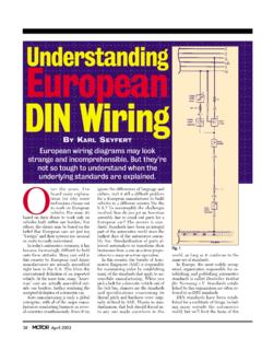
Understanding European DIN Wiring
www.e38.orgchart on pages 42 and 43 outlines many of the common terminal desig- ... gles, circles and symbols illustrate the components. Information about wire colors, terminal numbers, connectors, etc., are omitted to keep the diagram as ... gen. The lines across the top represent

Wiring diagram layout - Bentley Publishers
www.bentleypublishers.com11 - Component symbols (see page IV - VI) 12 - Wire cross-section size (in mm2)andwirecolors Abbreviations are explaining in color chart beside the wiring diagram. 13 - Component symbol with open drawing side Indicated component is continued on another wiring diagram. The number of corresponding wiring diagram can taken from list of contents.

Telescopic Handlers Operator’s Manual
midtnequipment.comA chart of standard hardware torques is located in the back of this manual. ... including gen-uine GEHL service parts. All parts should be obtained from or ordered through your GEHL dealer. Give complete ... 9’-11 1/2” (3.03 m) Outside turn radius: 13’-8” (4.2 m) Machine weight:
NORME EUROPÉENNE 1092-1 EN DAAD STAN EUROPEAN
www.htcflange.comForeword 3 Introduction 4 1 Scope 4 2 Normative references 5 3 Terms and definitions 7 3.1 DN 7 3.2 PN7 3.3 maximum aflowable pressure, PS 7 3.4 maximum atlowable temperature, TS 7 4 Designation 7 5 General requirements 8 5.1 Flange materials 8 5.2 Repairs 9 5.3 Bolting 9 5.4 Gaskets 9 5.6 Dimensions 10 5.8 Spot facing or back facing of flanges ...
Massachusetts Driver's Manual
www.mass.govThe policies in this Driver’s Manual include changes . that take effect on March 26, 2018. All other information you need to study for a learner’s

NOCO Genius GEN2 On-Board Battery Charger User Guide
newcontent.westmarine.com4.) Repeat steps 2 and 3 for each battery bank. 5.) When disconnecting the battery charger, disconnect in the reverse sequence, removing the NEGATIVE first. HOW TO START CHARGING 1.) Confirm that you have connected the eyelet terminal connectors properly. 2.) Connect the battery charger’s AC power plug into a suitable electrical outlet.

Doormerica - abs-abs.com
abs-abs.com• 2-3/4” Backset, 1-1/8”x 2-1/4” Face Plate, UL 3 Hour Fire Listed Stainless Steel Latch or Dead-latch. • 1-1/4” x 4-7/8” ANSI Strike. • Schlage “C” 6 Pin Keyway Standard. • Saturn, Sparta and Tubular Lever Design. • Barrier Free and Returns within 1/2” from the Door Face. • Door Thickness 1-3/4” -2” Options:

I N S T A L L A T I O N A N D I N S T R U C T I O N S
www.reliancecontrols.com2. Wire Stripper and Cutter (10 to 14 gauge) 3. Insulated Screwdrivers (#2 Phillips, 1/4" Flat Tip or #2 Square Tip depending on your load center) 4. Hammer 5. Marking Pencil 6. Tape Measure 7. Seven Wall Anchors with at Least a 3/8” Flange 8. Enough 10-3 with Ground Building Wire to reach from where you install your Outdoor Power Inlet Box ...