Example: dental hygienist
VIAVI Solutions Data Sheet VIAVI
SmartOTDR Handheld Fiber Tester ... Pulse widths 5 ns to 20 µs 5 ns to 20 µs 3 ns to 20 µs Event dead zone4 1.35 m 1.35 m 0.9 m Attenuation dead zone5 4 m 4 m 2.5 m Splitter attenuation dead zone Not available Not available 45 m after 15 dB splitter loss CW Light Source9
Tags:
Information
Domain:
Source:
Link to this page:
Documents from same domain

MAP Variable Optical Attenuator - viavisolutions.com
www.viavisolutions.com3 MAP Variable Optical Attenuator Specifications Parameter Single-Mode Multimode Standard With Output Power Monitor Standard With Output Power Monitor

VIAVI Solutions Data Sheet VIAVI
www.viavisolutions.comVIAVI Solutions Data Sheet VIAVI CellAdvisor™ JD785B Base Station Analyzer Spectrum Analyzer: 9 kHz to 8 GHz Cable and Antenna Analyzer: 5 MHz to 6 GHz
Cable Network Maintenance and Service Test Guide
www.viavisolutions.comThe following is a short list of cable network maintenance and service use cases. 2 Cable Subscriber Installation & Test Guide Use Case 1. Node Activation Performance Verification, Alignment, Troubleshooting Problem: As nodes are activated, the fiber connection must be tested with a power meter to verify that proper

Test and Measurement Solutions - viavisolutions.com
www.viavisolutions.comsolutions for line sweep measurement, RF / optical power measurements, and fiber inspection, all in a lightweight, cloud-enabled instrument ideal for cell site installation. Application

XPDR/DME TCAS/ADS-B/TIS/UAT TEST SET
www.viavisolutions.comSAFETY SYMBOLS IN MANUALS AND ON UNITS CAUTION: Refer to accompanying documents. (This symbol refers to ... 4.6.3 TIS-B GEN 1-2-4 107 4.6.4 TIS-B GEN Data 1-2-4 109 4.6.5 ADS-B GEN 1-2-4 109 ... Recommended Test Locations 1 …

G.709 – The Optical Transport Network (OTN)
www.viavisolutions.comto DWDM optical networks. The OTN is specified in the International Telecommunications Union (ITU-T) G.709 Network Node Interface for the OTN. This recommendation, sometimes referred to as digital wrapper (DW), takes single wavelength SONET/ SDH technology a step further enabling transparent, wavelength manageable multi-wavelength networks.
Related documents
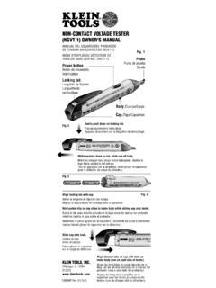
NON-CONTACT VOLTAGE TESTER (NCVT-1) OwNER’S …
data.kleintools.comScenario 1 – Powering on the tester: The “power on” LED in the tip of the tester changes from a steady green to a blinking green and a series of beeping sounds is generated. The tester then turns off. The unit is now deactivated and is not operational; the batteries require replacement. To …

DUAL RANGE NON-CONTACT VOLTAGE TESTER (NCVT-2) …
www.kleintools.comThe unit will beep 3 times and the power-on LED will switch from blue to green or green to blue. The tester will start in whichever mode it was last powered off in. Checking for the presence of AC voltage: Prior to use, test on known live circuit to verify tester functionality. Place tip of the tester near an AC voltage and refer

The Transistor Tester user manual
img.banggood.comThe Transistor Tester user manual Power: Transistor Tester can be powered from 6.8V – 12V DC. This can be achieve by a 9V layer-built battery. Two 3.7V Lithium-ion battery in series. Or AC adapter. When power on , the current is about 30mA at DC 9V. Control:

NS-468 Cable Manaual
ftaelectronics.comNS-468 Cable Tester Instruction Manual Revision 1.0 4-23-2008 Page -3- Testing RJ11 4 Conductor Phone Cables Phone cables are connected from Pin to Pin on the opposite end, 2-2, 3-3, and so forth. See diagram. NOTE: Pin 1 and Pin 6 are not connected. When testing RJ11 phone cables: Tester will test each pin sequentially.

Multi-function Tester (TC-V2.12k)
www.circuitspecialists.comShort press: Press the key and not less than 10 ms, release key within 1.5 seconds Long press: Press the key more than 1.5 seconds 2.2 Power on In the power off state, short press the multifunction key, the tester is turned on and automatically measured. Power on & measurement interface 2.3 Detect transistor

The Complete Guide to Electrical Insulation Testing
www.instrumart.comFigure 3–Typical scale on the Megger insulation tester. HoW To InTERPRET RESISTAnCE REAdInGS As previously mentioned, insulation resistance readings should be considered relative. They can be quite different for one motor or machine tested three days in a row, yet not mean bad insulation. What really matters is the trend

Manual-Ranging Digital Meter - Klein Tools
data.kleintools.com8 ENGLISH OPERATING INSTRUCTIONS DC CURRENT 200mA to 10A 1. For DC currents more than 200mA and less than 10A, insert RED test lead into 10A jack 3, and BLACK test lead into COM jack 4, and rotate function selector switch 2 to the 10A DC setting.

TESTING FOR VOLTAGE DROP
drivcat.com1. Connect the positive test lead of a Digital Volt/Ohm meter (DVOM) to the power source. Use of an analog meter is not recommended because damage to the meter could result from improper polarity. 2. Connect the negative test lead to the other end of the wire for the circuit being tested ( pointA). 3. Operate the circuit and observe the meter ...