Transcription of ZE500 Quick Reference Guide - Zebra Technologies
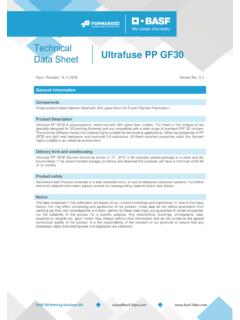
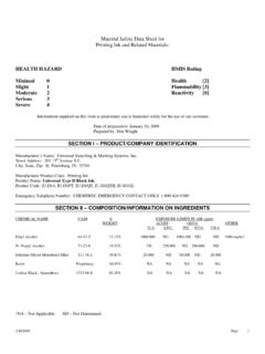
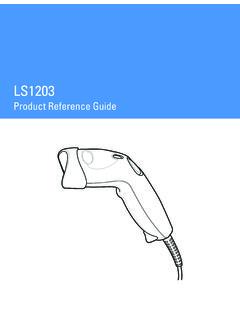
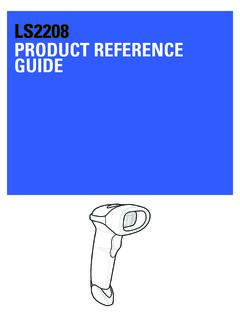
1 2011 ZIH Corp. All product names and numbers are Zebra trademarks, and Zebra and the Zebra logo are registered trademarks of ZIH Corp. All rights Rev. A03/08/2012ZE500 Quick Reference GuideUse this Guide to operate your print engine on a daily basis. For more detailed information, refer to the User Engine OrientationThe ZE500 print engines are available in a right-hand configuration (the print mechanism is on the right) and a left-hand configuration (the print mechanism is on the left).Figure 1 Left-Hand (LH) Print EngineFigure 2 Right-Hand (RH) Print Engine1231321media door2control panel3power switchZE500 Quick Reference GuidePrint Engine Components2P1047597-00103/08/2012 Print Engine ComponentsFigure 3 shows the components inside the media compartment of a right-hand print engine.
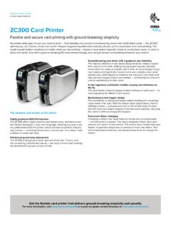
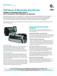
2 A left-hand unit contains a mirror image of these components. Familiarize yourself with these components before continuing with the print engine setup procedure. Figure 3 Print Engine Components (RH model shown)a2221ribbon take-up spindle7peel roller assembly (hidden when closed)2ribbon supply spindle8peel roller latch3printhead-release latch9media guide4printhead assembly10pinch roller assembly5peel bar11lower Guide post6platen roller12upper Guide post3491075612118123ZE500 Quick Reference GuideControl Panel03/08/2012P1047597-001 Control PanelAll controls and indicators for the print engine are located on the control panel (Figure 4). The power switch is located on top of the control 4 Control Panel1 The display shows the print engine s operating status and allows the user to navigate the menu light On when the print engine is USE l ig ht On when the print engine is light OffNormal operation no print engine print engine error exists.
3 Check the display for more light OffNormal operation. No data being received or print engine is processing data or is printing. No data is being print engine is receiving data from or sending status information to the host PAUSE button starts or stops print engine operation when FEED button forces the print engine to feed one blank label each time the button is CANCEL button cancels print jobs when the print engine is CALIBRATE button calibrates the print engine for media length and sensor LEFT ARROW navigates to the previous parameter in the PLUS (+) button changes the parameter values. Common uses are to increase a value, to scroll through choices, or to change values while entering the print engine MINUS (-) button changes the parameter values.
4 Common uses are to decrease a value, to scroll through choices, or to change the cursor position while entering the print engine SETUP/EXIT button enters and exits configuration RIGHT ARROW navigates to the next parameter in the Quick Reference GuidePreparing the Print Engine for Use4P1047597-00103/08/2012 Preparing the Print Engine for UseAfter you have familiarized yourself with the print engine components and the control panel, prepare the print engine for set up the print engine, complete these and inspect the print engine. If necessary, report any shipping damage. For more information, refer to the User the print engine in the preselected location or the female end of the A/C power cord into the A/C power connector on the back of the print When you are loading media or ribbon, remove all jewelry that could come into contact with the printhead or other print engine parts.
5 Caution Before touching the printhead assembly, discharge any built-up static electricity by touching the metal print engine frame or by using an anti-static wriststrap and Quick Reference GuidePreparing the Print Engine for Use03/08 the male end of the A/C power cord into an appropriate power the print engine to a computer using one or more of the available connections. The standard connections are shown here. A ZebraNet wireless print server option may also be present on your print portUSB portwired Ethernet portserial port115 V AC230 V ACZE500 Quick Reference GuidePreparing the Print Engine for Use6P1047597-00103/08 the media ribbon (if using thermal Transfer mode) and media into the print engine (see Load Ribbon and Media on page 7).
6 On (I) the print print engine boots up and performs a Quick Reference GuideLoad Ribbon and Media03/08/2012P1047597-001 Load Ribbon and MediaUse the instructions in this section to load ribbon (if used) and media in a ZE500 print engine. Ribbon is used with thermal transfer labels. For direct thermal labels, do not load ribbon in the print engine. For instructions for loading in different print modes, refer to the User load ribbon and media, complete these steps:Loading When you are loading media or ribbon, remove all jewelry that could come into contact with the printhead or other print engine parts. Important Use ribbon that is wider than the media to protect the printhead from wear. Ribbon must be coated on the outside (refer to the User Guide for more information).
7 Note For optimal printing quality and proper printer performance across our product line, Zebra strongly recommends the use of genuine Zebra supplies as part of the total solution. Specifically, the ZE500 print engines are designed to work only with genuine Zebra printheads, thus maximizing safety and print The printhead may be hot and could cause severe burns. Allow the printhead to the printhead-release latch to the open Quick Reference GuideLoad Ribbon and Media8P1047597-00103/08 the ribbon roll with the loose end unrolling in the direction the roll of ribbon on the ribbon supply spindle. Push the roll back as far as it will an empty ribbon core on the ribbon take-up spindle. Push the core back as far as it will Quick Reference GuideLoad Ribbon and Media03/08 the ribbon around the core on the ribbon take-up The printhead may be hot and could cause severe burns.
8 Allow the printhead to the ribbon under the lower ribbon Guide roller (1), under the printhead assembly(2), and then over the upper ribbon Guide roller (3).231 LHRH231 RHLHZE500 Quick Reference GuideLoad Ribbon and Media10P1047597-00103/08/2012 Loading media on the media supply reel of the applicator (refer to the applicator s documentation for more information). the release button on the pinch roller assembly. Allow the assembly to pivot the media Guide all the way Quick Reference GuideLoad Ribbon and Media03/08 the media under the upper Guide post (1), below the pinch roller assembly (2), and under the printhead assembly (3). approximately 30 in. (75 cm) of media past the peel bar. Remove and discard the labels from the liner on this exposed Quick Reference GuideLoad Ribbon and Media12P1047597-00103/08 in the media Guide until it just touches the edge of the down on the pinch roller assembly until it locks the printhead-release latch to the closed Quick Reference GuideLoad Ribbon and Media03/08 the peel roller latch so that the peel roller assembly pivots the liner around the peel bar, under the platen roller, and through the peel roller If the applicator has an air tube, route the liner between the air tube and the peel bar.
9 Do not thread the liner over the air Quick Reference GuideLoad Ribbon and Media14P1047597-00103/08 the peel roller assembly up until it locks into the closed the liner around the take-up spindle of the applicator (refer to the applicator s documentation for more information). the media Quick Reference GuideLoad Ribbon and Media03/08/2012P1047597-001 Remove Used RibbonRemove used ribbon from the ribbon take-up spindle each time you change the roll of remove used ribbon, complete these the ribbon run out? the core with the used ribbon off of the ribbon take-up the used ribbon. You may reuse the empty core from the ribbon supply spindle by moving it to the ribbon take-up the outContinue with step not run or break the ribbon before the ribbon take-up with step


![Comparison of typical 3D printing materials [1]](/cache/preview/1/a/9/9/7/6/e/f/thumb-1a9976efec209b805c79185b90d99fe7.jpg)