Transcription of Zero-current-switching switched-capacitor bidirectional DC ...
1 Zero-current-switching switched -capacitorbidirectional DC DC Lee and ChiuAbstract:The proposed Zero-current-switching switched -capacitor quasi-resonant DC DC con-verter is a new type of bidirectional power flow control conversion scheme. It possesses theconventional features of resonant switched -capacitor converters: low weight, small volume, highefficiency, low EMI emission and current stress. A Zero-current-switching switched -capacitor step-up/step-down bidirectional converter is presented that can improve the current stress problemduring bidirectional power flow control processing. It can provide a high voltage conversion ratiousing four power MOSFET main switches, a set of switched capacitors and a small resonantinductor. The converter operating principle of the proposed bidirectionalpower conversion schemeis described in detail with circuit model analysis.
2 Simulation and experiment are carried out toverify the concept and performance of theproposed bidirectional DC DC IntroductionThe switched -capacitor DC DC converter is a non-magnetic converter that requires only capacitor andMOSFET switches in the power stage. This converter hasthe following features; light weight, smaller size andfabrication on a semiconductor integrated circuit , the larger switching loss and current stress are theessential drawbacks in the conventional high-frequencyswitching DC DC converter [1 3]. Quasi-resonant conver-ters that are able to operate at constant switching frequencywith zero- current or zero-voltage switching (ZCS or ZVS)have been used to reduce the switching loss in the converterto overcome the aforementioned problems. This paperpresents a new Zero-current-switching switched -capacitorquasi-resonant (ZSC SC QR) converter that can operate athigh switching frequency with less switching loss forincreased converter efficiency with fewer switches[2, 3].
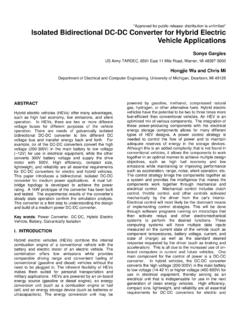
3 Although the ZCS SC QR converter has numerousadvantages, its power flow control moves only in the DC DC powerconversion is of greatinterest in systems fed by DCpower, including electricvehicle hybrid energy systems, fuel-cell systems and aero-space systems[4, 5]. The bidirectionality in these applica-tions involves current flow while the polarity of the DCvoltage at either end remains uncharged. Application inbattery equalisation schemes where the stronger energy ofthis system is transferred into the weaker energy subsystemusing the bidirectional power flow control scheme[6].A class of soft- switching bidirectional DC DC convertersis the expected candidate for applications such as unin-trerruptible power supplies (UPS), battery charging anddischarging systems, auxiliary power supplies in HEV, anddual voltage automotive systems[4, 6].
4 Aswitched-capacitor-based bidirectional DC DC converter providingthe capability of step-down/step-up voltage is proposed in[7]. The input/output current pulsating peaks of thebidirectional SC converter aremitigated, but the switchinglosses and the overall converter efficiency are not signifi-cantly improved[8, 9].This paper presents a new switched -capacitor step-up/step-down DC DC quasi-resonant bidirectional converterdesigned to operate at noninverting mode and constantfrequency. The proposed converter scheme can achievezero- current soft switching and reduce the MOSFET switching loss to increase the converter efficiency. Thehigh switching current stresses can also be reduced underthe bidirectional power flow control scheme[10].The proposed converter can be applied to many othertopologies for varying voltage conversion ratios undersuitable arrangement and designed control strategy of theswitched-capacitor networks.
5 A design example for thetriple-mode-tri-section-mode (three-mode/13-mode) ZCS SCQR converter was conducted to verify and validate thepredicted performance under bidirectional power flowcontrol. The EMI emissions in the power line source canalso be suppressed because of the soft switching and thesource current waveforms alongthe approximate Topologies descriptionFigure 1 shows the proposed noninverting type triple-mode/trisection-mode ZCS SC QR bidirectional converter thatwas developed based on the ZCS SC QR converter . Thecircuit is composed of four MOSFET main switchesparalleled with Schottky diodes. Only a very small inductorseries connected with a set of switched capacitors is neededto construct the resonant tanks in the converter . A resonantinductorLris connected in series with the switchingcapacitor comprised of C1and C2to achieve a resonantcycle when each of the switches Q1S(contains Q1 Pand Q1N)or Q2S(contains Q2 Pand Q2N) are switched on during theoperating interval.
6 The switches can be designed to switchThe authors are with the Department of Electronic Engineering, Fu-JenCatholic University, 510 Chung-Cheng Rd., Hsin-Chuang, Taipei 24205,Taiwan, Republic of ChinaE-mail: 2005 IEE Proceedingsonline no. 20050138 :20050138 Paper first received 22nd April and in final revised form 12th July 2005 IEE Power Appl., Vol. 152, No. 6, November 20051525on and off at zero- current state with theLr C resonantcurrent rising and falling to zero to achieve zero currentswitching for reducing the MOSFET switching loss. Theswitches Qa,Qband Qabare used to control the switchedcapacitors for parallel or series connection during thecharging or discharging states. Figure 2 shows a noninvert-ing type step-up ZCS SC QR DC DC converter undervarious operation switches Q1 Por Q1 Nand the switched -capacitor switches Qa,Qb,orQabcancontrol the forward power flow from the sourceV1to theother sourceV2as a triple-mode converter ( 3V1)shown as Fig.
7 2. The turn-on/off switches Q2 Por Q2 Nandthe switched -capacitor switching diodes Da,Db,orDabcanalso control the reverse power flow fromV2toV1as atrisection-mode converter ( V2/3), shown in Fig. the resonant currentILrincreases to a peak value anddecreases to zero current , it cannot reverse into negativecurrent because there is a diode in the resonant circuit loopof the converter that ceases current reversal. Figures 2a 2dand Figs. 3a 3dshow the equivalent circuit of the proposedbidirectional converterunder the forward and reversepower flow control proposed converter topology can be extendedto operate as a noninverting typen-mode/1n- mode andan inverting type double-mode/half-mode Zero-current-switching switched -capacitor quasi-resonant DC DCconverter for reconstructing the switched -capacitor config-uration in the capacitor bank.
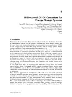
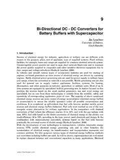
8 The following Sections ofthis paper analyse the proposed noninverting type triple-mode/trisection-mode ZCS SC QR bidirectional DC Circuit analysisThe equivalent circuit in Fig. 1 for the proposed noninvert-ing type ZCS SC QR bidirectional converter is shown inFigs. 2a 2dand Figs. 3a 3dunder the forward and reversepower flow control scheme for the various operating timeintervals. Some assumptionsare necessary to analyse thedynamic circuit behaviour: (i) the resonant inductorLrhas asmall inductance, neglecting internal resistance; (ii) thesemiconductor switches and diodes are ideal; and (iii) thecapacitors in the switched -capacitor bank are ideal. There-fore, the resonant currentILris controlled by the MOSFET switches Q1 Sand Q2 Sfor the forward and reverse powerflow control modes, respectively. The direction of thecontrolled power flow is determined according to theDaQaVc1+Vc2D2NQ1P+ V2D1PQ2ND2PQ1N+ D1NQ2 PDbQbV1C1 DabQabLrC2 +Fig.
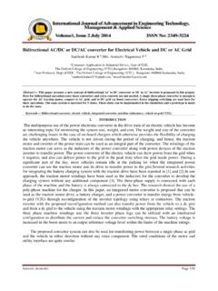
9 1 Triple-mode/trisection-mode ZCS SC QR bidirectionalDC DC converterC1 cV1V1C1 DaQaC2Vc2 Vc1D1PQ2NV2 ILr D1PQ2N+ILrbVc2C2 DaQaLrD1NQ2P++ Vc2D2PQ1 NLra+LrILrVc1 DbQbD2PQ1NC1V1D1NQ2PD2NQ1P DbQbDabQabDabQabD1PQ2NV2D2NQ1PD2PQ1ND2PQ 1NV2Vc2 DabQabD2NQ1 PDbQb+C2 DaQaILr+D1NQ2P +D2NQ1PC1V1 DbQbC2 D1PQ2ND1NQ2PV2Vc1Lr+DabQab DaQadVc1++ + + + + + + Fig. 2 Equivalent circuit of various operation stages for ZCS SCQR bidirectional DC DC converter with forward power flowat0otot1bt1otot2ct2otot3dt3otot41526 IEE Power Appl., Vol. 152, No. 6, November 2005switched-capacitor charging/discharging situation and/orthe desired power flow control orientation for the convertersystem. The corresponding switching waveforms of the ZCSSC QR bidirectional converter are also shown in Figs. 4aandbunder various power flow control schemes.
10 Thedetailed equivalent circuits for the proposed converterscheme are shown in Figs. 2a 2dat different time intervalsunder forward power flow control mode. The state spacedynamic of all the operation modes are easily analysed inthe following stages:Stage 1(Fig. 2a; t0otot1): The main switch Q1 Pandswitched-capacitor switches Qa,Qbare turned on att t0,the sourceV1provides current though MOSFET switchQ1P,D1P, the paralleled C1and C2, and the resonantreactanceLrstores the electric energy in the capacitorsCp C1+C2 2C. The dynamic state equation in thisinterval is given bydILr t dtdVC t dt264375 0 1Lr1CP0264375 ILr t VC t 1Lr000"#V1V2 1 with the initial conditionsILr(t0) 0andVC1(t0) VC2(t0) VC(t0) VC01. The solutions of (1) can beobtained asILr t V1 VC01 Zrsino1t 2 VC t V1 VC01 V1 coso1t 3 where the resonant angular frequency in stage 1 iso1 1=ffiffiffiffiffiffiffiffiffiffiLrCPp, the normalised impedance isZ1 ffiffiffiffiffiffiffiffiffiffiffiffiffiL r=CPp.