Transcription of Zone Panel Professional Installation Guide
1 HZ432 TrueZONE Zone Panel Professional Installation Guide69-2198-05 Installation GuideTABLE OF CONTENTSI nput Ratings:Voltage: 18-30 VAC 50/60 Hz transformer of 40 VA or Draw:Zone Panel : VA Wireless Adapter: 2 VA VA specifications at 24 :18- or 20-gauge solid (not stranded) Ratings:5% to 90% RH Ratings:Shipping: -20 to 150 F (-29 to 66 C)Operating: -40 to 165 F (-40 to 74 C)Dimensions:See Fig. :Complies with FCC Class B, part 15 ..iiApplication ..1 Accessories ..1 Mounting ..2 Wiring ..3 Heat Pump ..6 Dual Fuel ..8 Basic Configuration ..10 Advanced Configuration ..12 Operation ..13 Checkout ..13 Warranty ..14 Read and save these Help?For assistance with this product please visit and or call Honeywell Zoning Hotline toll-free at 1-800-828-8367 Registered Trademark. US Pat D562,261; D563,325; 7,558,648; 7,645,158; 7,693,591; 7,693,583; 7,766,246; 7,819,331; 7,904,830; 7,913,180; 7,957,839; 9,310,091 and other patents pending.
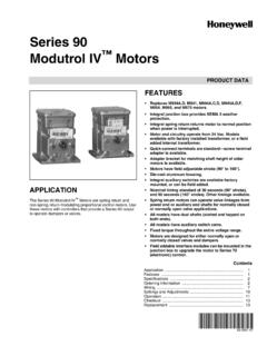
2 Copyright 2018 Honeywell International Inc. All rights (341) (47)8 (203)Fig. 1. HZ432 TrueZONE Panel dimensions in in. (mm).SPECIFICATIONSHZ432 TrueZONE 1 69-2198 05 ACCESSORIESThe HZ432 TrueZONE Panel controls: Single-stage, multi-stage, conventional, or heat pump heat/cool HVAC equipment up to 3 stages of heat and 2 stages of cool; Dual-fuel systems with up to 2 heat pump stages and 2 fossil fuel stages; 2, 3, or 4 zones and is expandable to 32 zones using wired thermostats with the TotalZone Add-A-Zone Panel ; 2, 3, or 4 zones with wireless thermostats when used with the wireless refer to TrueZONE Panel Frequently Asked Questions form 50-9694 for operating details, or see 1.
3 Recommended , TH3110D, T87 NTH8110U, TH6110D, TH4110 DMulti-StageTH5220 DTH8320U, TH8321U, TH6220D, YTH9421 CHeat-PumpTH5220D (2H/1C only) TH3210D (2H/1C only) TH5320U* (Up to 3H/2C)TH8320U (Up to 3H/2C) TH8321U (Up to 3H/2C) TH6320U* (Up to 3H/2C) TH6220D (2H/1C only) TH4210D (2H/1C only) YTH9421 CWire-less TH5320 RTH6320R* This thermostat cannot control two stages of fossil fuel when in emer-gency heat mode. For RedLINK wireless devices, a THM4000 is required. For more than 4 zones, see page 2. Recommended (6 VA)ZD (6 VA)ZonePower-open/power-closedRRD (2 VA)BypassBarometricSPRDSPRDC ommercialZonePower-open/power-closedMARD (2 VA)D2 or D3 with ML6161A2009 (2 VA)BypassPower-open/power-closedMARD (2 VA) with SPCD2 with ML6161B2024* (2 VA) and SPC* Or equivalent damper and 3. Maximum Dampers.*Ambient Damper VA per Zone100 F (38 C) F (71 C) * Use an SDCR (Slave Damper Control Relay) for additional dampers to surpass the maximum damper VA per zone.
4 Maximum dampers per Panel is limited by transformer size. Ensure transformer is large enough to power the Panel , thermostats, wireless adapter module, and 4. VA transformer*AT140A104275 VA transformerAT175A1008 Discharge Air Temperature Sensor (DATS)*C7735A1000 TAZ-4 TotalZone Add-A-ZoneTM Control PanelSDCR**Slave Damper Control RelayPortable Comfort Control**REM5000R1001 Wireless Adapter**THM4000R1000 Wired Outdoor Air Temperature Sensor C7089U1006 (hard wired)Wireless Outdoor Air Temperature Sensor** C7089R1013 (wireless)RedLINK Internet Gateway**THM6000R1002** Included in HZ432K kit.** Use an SDCR (Slave Damper Control Relay) to add additional dampers to a zone to surpass the maximum Damper VA rating per Zone.** For RedLINK wireless devices, a THM4000 is required. A wired or wireless outdoor sensor is required for Dual Fuel Guide69-2198 05 2 MOUNTINGM ount the HZ432 TrueZONE Panel near the HVAC equipment; locate it on a wall, stud, roof truss, or cold-air : The HZ432 TrueZONE Panel can be mounted in any orientation; level it for appearance the zone Panel cover from the base, and use the base as a template to drill mounting the base to the wall, stud, roof truss, or duct with appropriate screws (not included).
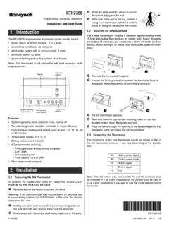
5 Use two screws for attaching to a stud or roof truss, or four screws for duct or drywall/plaster 2 Fig. 3 SUPPLYDUCTDATS(AT LEAST 3 FTFROM PLENUM)DATS(ALTERNATELOCATION)TrueZONE PANELMOUNTED ONRETURN DUCTTrueZONE PANELMOUNTED ON WALLZD SERIESZONE DAMPERSSPRD BYPASSDAMPERFURNACE ORAIR CONDITIONERM24738M24807HZ432 TrueZONE 3 69-2198 05 WIRINGF ollow these steps for wiring all systems. However, wiring will vary depending on equipment. For conventional sys-tems, see page 5. For heat pump systems, see pages 6 and 7. For dual fuel systems, see pages 8 and must comply with applicable codes, ordinances, and regulations. Use the following wiring diagrams to wire the zone Panel to the thermostats and HZ432 offers many innovations for wire management and organization: wires can be run behind the Panel , through wire channels on its sides, and must be attached to a wiring anchor with a cable thermostats using instructions provided with using wired thermostats, connect thermostat to zone Panel .
6 To con-nect wire to the Panel , strip approximately 1/4 in. of insulation and push wire into terminal. To release wire, press the button on top of the dampers using instructions provided with dampers to zone : Multiple dampers can be wired in 4 DAMPERTHERMOSTATCAUTION: Voltage Hazard. Can cause electrical shock or equipment damage. Disconnect power before beginning Installation . Wire entire Panel before applying transformer 4 Fig. 5 Fig. 6M24920 ARD OR ZD DAMPER SPRING-OPEN POWER-CLOSEDZONE 3 DAMPERM1M4M6 RZONE 1 DAMPERRRD OR MARD DAMPER POWER-OPEN POWER-CLOSEDM4 OPENM6 CLOSEDM1 COMMONARD OR ZD DAMPER SPRING-OPEN POWER-CLOSEDZONE 2 DAMPERI nstallation Guide69-2198 05 4 The DS/BK terminal is used with a variable-speed fan. If the HVAC equipment has DS, BK, ODD, or DHUM ter-minals, wire that terminal to the DS/BK terminal.
7 When greater than 25% of zones are calling for cooling, this terminal will be energized and the fan will operate at normal speed. When 1 zone or fewer than 25% of zones are calling for cooling, the terminal will be de-energized and the fan will run at a reduced rate, which will reduce the amount of air that needs to be bypassed. This reduc-es blower speed on most variable speed blowers. Refer to HVAC equipment manufacturer oil heat with a separate transformer for cooling, remove this jumper. For other systems, leave jumper in place and wire to HVAC R terminal with 18 gauge solid copper DATS as equipment as shown here or on pages 5 a dedicated transformer as (HOT)L2 RHRCW1/EW2W3Y1Y2 GOBDS/BKM24809 HVACFAN RELAY24 VOLT 7 Fig. 9 Fig. 118 When a wireless thermostat, Portable Comfort Control, wireless outdoor air temperature sensor, or other RedLINK wireless device is used on systems up to four zones, wire the THM4000 Wireless Adapter Module to the ABCD terminals on the zone systems with more than 4 zones, see page SETUPFig.
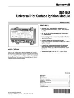
8 10 Connect outdoor air temperature sensor as shown. Required for dual fuel systems; optional for other multistage systems. If using the C7089R1013 wire-less outdoor sensor and THM4000R wireless adapter on 2- to 4-zone systems, see page 8M28207 OTOTSENSORSC7089U1006 OUTDOORTEMPERATURESENSORCAUTION: Do not wire the A-B-C-D terminals of the THM5320R Wireless Equipment Interface Module to the A-B-C-D terminals on the HZ322 zone control Panel . Doing so will damage the TrueZONE 5 69-2198 05 CONVENTIONALThe following diagram is an overall view of wiring for a conventional system as depicted in steps 3 1 HEAT 2 HEAT 3 COOL 1 COOL 2 PURGEFANEM HEATZONE 1 ZONE 2 ZONE 3 ZONE 4 EMERGENCYHEATM1M4M6 RCW1/EW2W3Y1Y2GO/BLM1M4M6 RCW1/EW2W3Y1Y2GO/BLM1M4M6 RCW1/EW2W3Y1Y2GO/BLRHRCW1/EW2W3Y1Y2 GOBDS/BKHOMECONFIGCHECK OUTADJUST SETTINGM4 OPENM6 CLOSEDM1 COMMONM28196 AARD OR ZD DAMPERSPRING-OPENPOWER-CLOSEDDEDICATEDTR ANSFORMERRCL1(HOT)
9 L2 ARD OR ZD DAMPERSPRING-OPENPOWER-CLOSEDARD OR ZD DAMPERSPRING-OPENPOWER-CLOSEDM1M4M6 RCW1/EW2W3Y1Y2GO/BLDATSDATSOTOTAZ1AZ2 ZONE 4 DAMPERTHERMOSTATEQUIPMENTPOWERSENSORSACC ESSORIESZONE 2 DAMPERTHERMOSTATZONE 1 DAMPERTHERMOSTATZONE 3 DAMPERTHERMOSTATRCC7089U1006 OUTDOORTEMPERATURESENSORC7735A1000 DATSABCDWIRELESSADAPTERWIRELESSHVACFAN RELAY24 VOLT OR MARD DAMPERPOWER-OPENPOWER-CLOSEDCONNECTPOWER THM4000 RCONNECTEDWIRELESS SETUP11 FOR OIL HEAT WITH A SEPARATE TRANSFORMER FOR COOLING, REMOVE JUMPER. 22 ABCD TERMINALS FOR THE THM4000R WIRELESS ADAPTER ONLY. NEVER WIRE A THM5320R WIRELESS EIM TO THESE 12. Zone Panel wiring Guide69-2198 05 6 HEAT PUMPFig. 13. Zone Panel wiring heat pump, 2-heat/1-cool with electric auxiliary the following diagram for wiring a 2-heat/1-cool heat pump with electric auxiliary : You can use a conventional thermostat for a heat pump system; however, em heat can only be controlled by heat pump thermostats or by pressing the Emergency Heat button on the zone Panel .
10 The diagram below shows a heat pump thermostat used with a heat pump LABELED W2 ON SOME THERMOSTATS WITH SEPARATE O AND B TERMINALS, ATTACH O FORCOOL CHANGEOVER VALVES OR ATTACH B FOR HEAT CHANGEOVER EQUIPMENT DOES NOT HAVE SEPARATE E AND AUXILIARY TERMINALS, JUMPERE TO W2 ON Panel AND WIRE TO 1 HEAT 2 HEAT 3 COOL 1 COOL 2 PURGEFANEM HEATZONE 1 ZONE 2 ZONE 3 ZONE 4 EMERGENCYHEATM1M4M6 RCW1/EW2W3Y1Y2GO/BLM1M4M6 RCW1/EW2W3Y1Y2GO/BLM1M4M6 RCW1/EW2W3Y1Y2GO/BLRHRCW1/EW2W3Y1Y2 GOBDS/BKHOMECONFIGCHECK OUTADJUST SETTINGM4 OPENM6 CLOSEDM1 COMMONM24794 BARD OR ZD DAMPERSPRING-OPENPOWER-CLOSEDDEDICATEDTR ANSFORMERRCL1(HOT)L2 AIRHANDLERFAN RELAYEM. HEATAUX. HEATHEAT PUMPGY24 VOLT OR ZD DAMPERSPRING-OPENPOWER-CLOSEDARD OR ZD DAMPERSPRING-OPENPOWER-CLOSEDM1M4M6 RCW1/EW2W3Y1Y2GO/BLDATSDATSOTOTAZ1AZ2 ZONE 4 DAMPERTHERMOSTATEQUIPMENTPOWERSENSORSABC DACCESSORIESZONE 2 DAMPERTHERMOSTATZONE 1 DAMPERTHERMOSTATZONE 3 DAMPERTHERMOSTATRCC7089U1006 OUTDOORTEMPERATURESENSORC7735A1000 DATSWIRELESSADAPTERRRD OR MARD DAMPERPOWER-OPENPOWER-CLOSEDREVERSINGVAL VEWIRELESSCONNECTPOWERTHM4000 RCONNECTEDWIRELESS SETUP44 ABCD TERMINALS FOR THE THM4000R WIRELESS ADAPTER ONLY.