Transcription of Zone Panel Professional Installation Guide
1 Zone Panel Professional Installation GuideHZ221 TrueZONE69-2200-01 Installation Guide 69-2200 0 TablE Of CONTENTsRead and save these Help?For assistance with this product please visit or call Honeywell Zoning Hotline toll-free at 1-800-828-8367 Registered Trademark. Patents 2008 Honeywell International Inc. All rights and Accessories ..1 Installation ..2 Wiring ..3 Operation ..5 Warranty ..6HZ22 TrueZONE 69-2200 0 spECifiCaTiONs aNd aCCEssOriEsInput Ratings:Voltage: 18-30 VAC 50/60 Hz transformer of 40 VA or Draw:Zone Panel : VA VA specifications at 24 :18 20-gauge solid (not stranded) Ratings:5% to 90% RH Ratings:Shipping: -20 to 150 F (-29 to 66 C)Operating: -40 to 165 F (-40 to 74 C)Dimensions:See :Complies with FCC Class B, part 15 (203)8-1/8(206)1-55/64(47)HZ221 TrueZONE Panel dimensions in in.
2 (mm).RECOMMENDED THERMOSTATS, DAMPERS, AND ACCESSORIESThe following are suggested thermostats, dampers, and accessories for use with the TrueZONE 1. Recommended PumpTH3210D, TH5220D, TH5320 UTH4210D, TH6220D, TH8220U, TH8321U, YTH9421 CNote: These thermostat models all have different four-digit suffixes. All versions of the model numbers listed above will work with the applications they're listed 2. Recommended DamperRoundRectangularZoneSpring-open/po wer-closedARDZDZonePower-open/power-clos edMARD/RRDFor recommended dampers call the Honeywell Zoning Hotline at pres-sure regulat-ing damperSPRDSPRDT able 3.
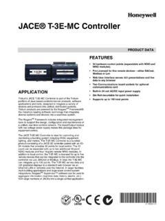
3 Maximum Dampers.*Ambient Damper VA per Zone100 F (38 C) F (71 C) * Use an SDCR (Slave Damper Control Relay) for addi-tional dampers. Maximum dampers per Panel is limited by transformer size. Ensure transformer is large enough to power the Panel ( VA) and 4. VA transformer*AT140A1042*75 VA transformerAT175A1008 Discharge Air Temperature Sensor (DATS)*DATS C7735A1000*SDCRS lave Damper Control Relay* Included in HZ221K Guide69-2200 0 2 69-2200 0 iNsTallaTiONMount the HZ221 TrueZONE Panel near the HVAC equip-ment; locate it on a wall, stud, roof truss, or cold-air : The HZ221 TrueZONE Panel can be mounted in any orientation.
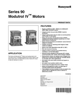
4 Level it for appearance Panel (DUCT MOUNT)ZONE Panel (WALL MOUNT)ARDDAMPERSDATS(ALTERNATE LOCATION)Separate the zone Panel cover from the base, and use the base as a template to drill mounting the base to the wall, stud, roof truss, or duct with appropriate screws (not included).2 Use two screws for attaching to a stud or roof truss, or four screws for duct or drywall/plaster 0 2HZ22 TrueZONE 69-2200 0 WiriNgInstall thermostats using instructions provided with thermostat to zone Panel . To connect wire to the Panel , strip approximately 1/4 in. of insulation and push wire into terminal.
5 To release wire, press the button on top of the terminal. In retrofit applica-tions, trim end of wire if not the thermostat has separate E and Aux terminals, install a jumper between the two can be run behind the Panel , through wire channels on the Panel 's sides, and must be attached to a wiring anchor with a cable 2 THERMOSTATM28234 BRCEAUXYGO/BLZONE 2 DAMPERTHERMOSTATM1M4M6 RCE/AUXYGOLW iring must comply with applicable codes, ordinances, and dampers using instructions provided with dampers. Connect dampers to zone : Multiple dampers can be wired in OR ZD DAMPERSPRING-OPEN POWER-CLOSEDZONE 2 DAMPERM1M4M6 RZONE 1 DAMPERRRD OR MARD DAMPER POWER-OPEN POWER-CLOSEDM4 OPENM6 CLOSEDM1 COMMONARD OR ZD DAMPER SPRING-OPEN POWER-CLOSEDZONE 2 DAMPERCAUTION: Voltage Hazard.
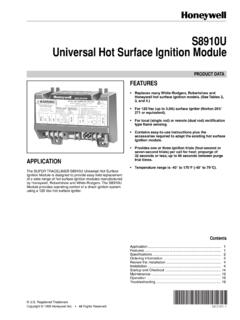
6 Can cause electrical shock or equipment damage. Disconnect power before beginning Installation . Wire entire Panel before applying transformer DATS as Guide69-2200 0 69-2200 0 The DS/BK terminal is used with a variable-speed fan. Connect to the DS, BK, or ODD terminal on the furnace equipment. When only one zone calls for heat, cool, or fan, the DS/BK terminal operates the fan at low speed to reduce transformer as equipment as TRANSFORMERRCM28237 RCPOWERL1(HOT)L2M28236 AEQUIPMENTRCE/AuxYGOBDS/BKLAIRHANDLERFAN RELAYAUX/EM HEATHEAT PUMPGY24 VOLT RELAYAUX HEATHEAT PUMPGY24 VOLT 2 THERMOSTATARD OR ZD DAMPER SPRING-OPEN POWER-CLOSEDPURGE OVERRIDEEQUIPMENTM4 OPENM6 CLOSEDM1 COMMONM1M4M6 RCE/AUXYGOLTHERMOSTATRCEAUXYGO/BLRRD OR MARD DAMPER POWER-OPEN POWER-CLOSEDM1M4M6 RCE/AUXYGOLTHERMOSTATZONE 1 DAMPERZONE 2 DAMPERDEDICATEDTRANSFORMERL1(HOT)
7 L2 RCC7735A1000 DATSDATSRCHEATCOOLFANPURGEZONE 1 ZONE 2EM HEATEMERGENCY HEATPOWERSENSORThe following diagram is an overall view of wiring for a heat pump system as depicted in steps 3 0 HZ22 TrueZONE 69-2200 0 The HZ221 TrueZONE Panel contains an LED display that communicates system and zone status. The LEDs indicate the following 1 ZONE 2 EM HEATM28239 ALED 5. LED when in heat. Blinking when DATS temperature exceeds 120 F (49 C) and calling for heat pump only. Blinking when DATS temperature exceeds 160 F (71 C) and calling for heat pump and auxiliary heat. At 150 F (66 C), auxiliary heat is when in cool.
8 Blinking when 45 F (7 C) DATS low limit mode has been when in when in purge (lasts 2 minutes at power-up and after a call for heat or cool). Blinking when the DATS sensor has failed, or the wires are shorted or open. Will blink for 3 minutes at power-up if DATS is not 1, 2 Solid green when open or red when closed or amber when there is a damper or thermo-stat short circuit (circuit breaker trip).EM HEATS olid when in Em Heat Zones, 2H/1 CLED StatusHeat LED Heating ModeFlashing Heat LED High LimitCool LED Cooling ModeFlashing Cool LED Low LimitPurge LED Purge ModeFlashing Purge LED Sensor FailureFan LED Fan OnZone LEDs Green - Open Red - Closed Flashing - ShortZone NamesZone 1 _____Zone 2 _____Technical Support: Pending 50031314-001 Rev.
9 AM28240 AEm Heat LED Em Heat ModeMuch of this information is also listed on the label on the inside of the HZ221 the zone Panel cover is off, the EMERGENCY HEAT/PURGE OVERRIDE button is the Panel is in Purge (at startup or after a call for heat/cool), pressing this but-ton stops the Purge, which saves time during Installation or other times, pressing the button puts the zone Panel into Em Heat mode so that all calls for heat are handled by the auxiliary 1 ZONE 2 ZONE 3 ZONE 1 DAMPERTHERMOSTATRCDATSDATSEQUIPMENTPOWER SENSORZONE 3 DAMPERTHERMOSTATZONE 2 DAMPERTHERMOSTATPURGE OVERRIDEEMERGENCY HEATH oneywell International Douglas Drive NorthGolden Valley, MN and Control SolutionsHoneywell Limited-Honeywell Limit e35 Dynamic DriveToronto.
10 Ontario M1V 4Z9 Printed in on recycled paper containing at least 10% post-consumer paper fibers. Registered Trademark. 2008 Honeywell International pending69-2200 01 04-08 WarraNTyHoneywell warrants the products in this catalog (except those parts designated on Honeywell s price lists as not covered by this warranty) to be free from defects due to workmanship or materials, under normal use and service, for the following warranty periods. Honeywell VisionPRO , Commercial VisionPROTM, FocusPRO , PRO 4000, PRO 3000, LineVoltTM PRO, Digital RoundTM, and Modern RoundTM (T87K, N) Series Thermostats with a date code of 0501 or later: sixty (60) months from date of Installation .