On A Typical Current Transformer
Found 8 free book(s)
'Magnetics Design 5 - Inductor and Flyback Transformer …
www.ti.comtypical peak-peak triangular ripple current 20% of Idc, or 2A (worst at high Vin). In this example, the worst-case rms ripple current is 0.58A (triangular wave-form rms equals I pp / .Jj2 ), and rms ripple current squared is only .333, compared with the dc current squared of 100. Thus, for the ac f R loss to equal the
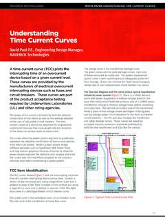
Understanding Time Current Curves - Maverick Technologies
www.mavtechglobal.comThe transformer inrush current is also plotted as a single point on the TCC diagram. Again, as part of the initial design, the transformer inrush current must be to the left of the transformer primary fuse curve otherwise the fuse will open when the transformer is energized. These differences in the unbalanced and 100% damage curves can
Federal Pacific Medium Voltage Transformer Catalog
federalpacific.comload losses) in the transformer when carrying full rated load. These losses consist primarily of I2R losses in the primary and secondary winding and ensure that specifications of the transformer design are met. Excitation Current Testing determines the current necessary to maintain transformer excitation.
Lesson 11: Transformer Name Plate Data and Connections
www.engr.siu.eduIdentify transformer polarity using dot and conventional labeling. Explain and interpret information found on transformer name plates. Compare and contrast the performance of three phase transformer connections. Indentify the schematic symbols of potential and current transformer. List characteristics on these devices and explain how
Lesson 9: Practical Transformer Model and Calculations
www.engr.siu.eduTypical values: 3-5% of rated for large power transformers. Transformer Voltage Drop and Impedance Lesson 9_et332b.pptx 18 Example 9-2: The equivalent resistance and reactance of a 50 kVA, 2400-480 V transformer's windings are R = 2.80 W and X = 6.00 W. (high side). A load of 10 20o is connected to the low voltage side. Determine:
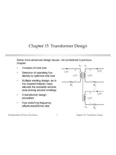
Chapter 15 Transformer Design
ecee.colorado.eduFundamentals of Power Electronics Chapter 15: Transformer design3 15.1 Transformer Design: Basic Constraints Core loss Typical value of for ferrite materials: 2.6 or 2.7 B is the peak value of the ac component of B(t), i.e., the peak ac flux density So increasing B causes core loss to increase rapidly This is the first constraint P fe = K fe ...

Transformer solutions across the grid
www.prolecge.com• Meets or exceeds current RUS, NEMA and ANSI Standards C57.12.00, ANSI C57.12.20 as applicable ... transformer while allowing straight cable configuration with only a small increase in height. ... Overall typical dimensions for reference kVA Height Width Depth Typ Weight Typ Gal (Lb) Oil 75 66 66 69 69 69 74 75 78 83 86 87 46 46 46 50 53 62 ...
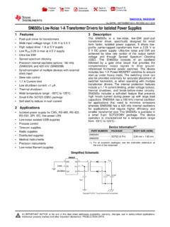
SN6505x Low-Noise 1-A Transformer Drivers for Isolated ...
www.ti.comtransformer drivers. The internal protection features include a 1.7 A current limiting, under-voltage lockout, thermal shutdown, and break-before-make circuitry. SN6505x includes a soft-start feature that prevents high inrush current during power up with large load capacitors. SN6505A has a 160 kHz internal oscillator