10th Generation Intel Core™ Processor Families
Document Number: 341077-005 10th Generation Intel® Core™ Processor Families Datasheet, Volume 1 of 2 Supporting 10th Generation Intel® Core™ Processor Families, Intel® Pentium® Processors, Intel® Celeron® Processors for U/Y Platforms, formerly known as Ice Lake July 2020
Download 10th Generation Intel Core™ Processor Families

Information
Domain:
Source:
Link to this page:
Documents from same domain

Intel® AMT Configuration Utility User Guide
www.intel.comIntel® AMT Configuration Utility . User Guide . Version 11.0 . Document Release Date: December 17, 2015

Land Grid Array (LGA) Socket and Package …
www.intel.com3. Introduction. In this document, Intel has integrated customer feedback and developed a reference process to serve as a manufacturing enabling solution.

Microcode Revision Guide - intel.com
www.intel.comMicrocode Update Guidance Code Name Product Collection Product Names Vertical Segment CPUID Platform ID OS Update for Q2 Production Status Pre-Mitigation

U.S. Intern Relocation Guide (Including Canada)
www.intel.comFINDING HOUSING You are responsible for arranging your own housing needs, up to and including signing the lease, ordering rental furniture, paying deposits and setting up utilities.

DrMOS Specifications - Intel
www.intel.comTechnical Specifications R 7 3 Technical Specifications The feature set for the DrMOS can be divided into two major areas. They address the electrical

Intel Stratix 10
www.intel.comIntel® Stratix® 10 Intel ® StratIx® 10 Mx (DraM SySteM-In-Package) ProDuct table Notes: 1. LE counts valid in comparing across Intel FPGA devices, and …

Intel® Intel® Command Line InterfaceCommand …
www.intel.comIntel® Intel® Command Line InterfaceCommand Line InterfaceCommand Line Interface ... Intel® Command Line Interface Features and ... • Linux* command shell .

Data Sheet: MAX 3000A Programmable Logic …
www.intel.comAltera Corporation 3 MAX 3000A Programmable Logic Device Family Data Sheet The MAX 3000A architecture supports 100 % transistor-to-transistor logic

256 10 GX, MX, TX, and SX Device Family Pin …
www.intel.comIntel® Stratix® 10 GX Pin Connection Guidelines Clock and PLL Pins Note: Intel recommends that you create an Intel ® Quartus Prime design, enter your device I/O assignments, and compile the

256 10 L- and H-Tile Transceiver PHY User Guide - …
www.intel.comIntel® Stratix® 10 L- and H-Tile Transceiver PHY User Guide Subscribe Send Feedback UG-20055 | 2018.07.06 Latest document on the web: PDF | HTML
Related documents

400KHz 60V 2A Switching Current Boost / Buck-Boost ...
www.xlsemi.com400KHz 60V 2A Switching Current Boost / Buck-Boost / Inverting DC/DC Converter Rev 1.2 www.xlsemi.com 2 Pin Configurations XL6007 1 3 5 2 4SW EN FB VIN NC 6 7 8 SW GND GND Figure2. Pin Configuration of XL6007 (Top View) Table 1 Pin Description Pin Number Pin Name Description 1 EN
Number of parameters (M)
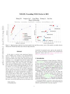
arxiv.orgthe above techniques, we boost the YOLOv3 to 47.3% AP (YOLOX-DarkNet53) on COCO with 640 ture of DarkNet53 backbone and an SPP layer, referred640 res-olution, surpassing the current best practice of YOLOv3 (44.3% AP, ultralytics version2) by a large margin. More-over, when switching to the advanced YOLOv5 architec-

DESIGN OF SINGLE PHASE BOOST POWER FACTOR …
web.wpi.eduboost power factor correction circuit and design of its control system. 1.2 Disadvantage due to Harmonic Current in Power Grid [2] In fact, the decrease of power factor caused by harmonic current already exists for a long time. People don’t pay much attention because the use of switching devices is not
LTC3780 (Rev G) - Analog Devices
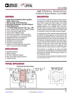
www.analog.com4-Switch Buck-Boost Controller The LTC®3780 is a high performance buck-boost switch - ing regulator controller that operates from input voltages above, below or equal to the output voltage. The constant frequency current mode architecture allows a phase-lockable frequency of up to 400kHz. With a wide 4V to
TOP VIEW - Diodes Incorporated
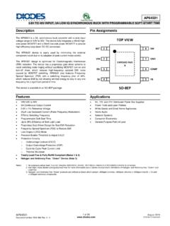
www.diodes.comHigh-Side Gate Drive Boost Input. BST supplies the drive for the high-side N-Channel power MOSFET. A 100nF capacitor is recommended from BST to SW to power the high-side driver. VIN 2 Power Input. VIN supplies the power to the IC as well as the step-down converter power MOSFETs. Drive VIN with a 3.8V to 40V power source.
Switching regulator fundamentals (Rev. C)
www.ti.comThis paper will detail the operating principles of the four most commonly used switching converter types: Buck— used to reduce a DC voltage to a lower DC voltage. Boost— provides an output voltage that is higher than the input. Buck-Boost (invert)—an output voltage that is generated opposite in polarity to the input.

Buck-Boost DC-DC Converter 25A / 50A / 100A
www.victronenergy.comrelated programmable time-delayed switching. This also prevents the onboard voltage of the vehicle from becoming too low. It is not necessary to intervene in the system of the vehicle, install a separate motor run sensor or intervene in the CAN bus system. Apart from this detection, the Buck-Boost series equipment can also be switched on with a