
Appendix A Eigenvalue Buckling Analysis
Eigenvalue or linear buckling analysis predicts the theoretical buckling strength of an ideal linear elastic structure. This method corresponds to the textbook approach of linear elastic buckling analysis. •The eigenvalue buckling solution of a Euler column will …
Download Appendix A Eigenvalue Buckling Analysis

Information
Domain:
Source:
Link to this page:
Documents from same domain
1 Finite Element Analysis Methods - Rice University
www.clear.rice.edu1 Finite Element Analysis Methods ... it is often referred to as finite element analysis (FEA). FEA is the most common tool for stress and structural ...

Lecture 1 Introduction to ANSYS Workbench - Rice …
www.clear.rice.eduThis training course covers the basics of using ANSYS Mechanical in performing structural and thermal analyses. It is intended for all new or occasional ANSYS Mechanical users, regardless

Types of Control: Open loop, feedback, feedforward
www.clear.rice.eduFeedback Control “Understand Your Technical World” ... • or better, why do you need a control system at all? • consider ovens, A/C units, airplanes, manufacturing, pumping stations, etc ... Design of dynamics through feedback Allows the dynamics (behavior) of the system to be modified ...

Lecture 9 Thermal Analysis - Rice University
www.clear.rice.eduthermal resistance. q TCC T target T contact The amount of heat flow across a contact interface is defined by the contact heat flux expression ^q” shown here: • T contact is the temperature of the contact surface and • T target is the temperature of the target surface. … Thermal ontact
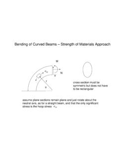
curved beam strength - Rice University
www.clear.rice.edukr σθθ=− − + = r r ... iar r m ari y r i r iar m yri ari ayri ar r m yrai r

Introduction to ANSYS Mechanical
www.clear.rice.edu– The “2D” switch must be set on the Project page prior to importing geometry. •Each node in a 2D element has two translational degrees of freedom (UX and UY) for structural or one temperature DOF for thermal. •2D solids are used to represent three types of 3D geometry, “Axisymmetric”, “Plane stress” and “Plane strain”.

8 Flat Plate Analysis - Rice University
www.clear.rice.eduThen, the plots are pretty, but wrong. If the edges of the plate are simply sitting on top of to walls, then the wall could not pull down on the corner. ... reaction forces appear, then move the split line away from the corner and repeat the process. It may be a slow procedure, but it can lead you to the correct lift off regions. ...

Lecture 7 Static Structural Analysis
www.clear.rice.edu•Thermal expansion coefficient is required if a temperature load is applied. ... Example: a Frictionless Support applied to the face of the block shown would indicate that the Z degree of freedom is no longer free (all other DOF are free). ... –Adjustment (length)

12 Buckling Analysis - Rice University
www.clear.rice.eduthose terms even though finite element analysis lets you conduct buckling studies in 1D, 2D, and 3D. For a material, stiffness refers to either its elastic modulus, E, or to its shear modulus, G = E / (2 + 2 v) where v is Poisson’s ratio.
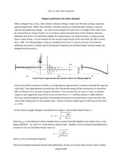
Impact Load Factors - Rice University
www.clear.rice.eduMaximum horizontal stress (143 MPa) is at the center plane top and bottom Of course, since the static model is linear there is no need to re-run the model (unless you want pretty plots). The static maximum fiber stress (SX) of 26.0 MPa could be multiplied by the 5.48 vertical Impact Factor to find the dynamic maximum SX stress of 143 MPa.
Related documents
Chapter 3 Short Column Design - Engineering
by.genie.uottawa.cacolumn is initiated either by the material failure of a section, or instability of the column as a member, depending on the level of slenderness. The latter is known as column buckling. Design of slender columns is discussed in Chapter 4. The classification of a column as a “short column” or a “slender column” is made on the basis of its
Design of Beams (Flexural Members) (Part 5 of AISC/LRFD)
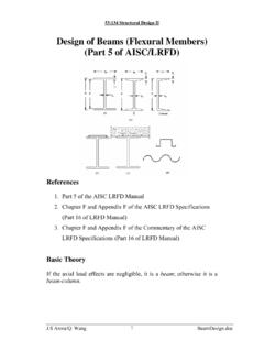
user.engineering.uiowa.educolumn. Thus, in beams covering long spans the compression flange may tend to buckle. However, this tendency is resisted by the tensile flange to certain extent. The overall effect is a phenomenon known as lateral torsional buckling, in which the beam tends to twist and displace laterally. Lateral torsional buckling may be prevented by: 1)
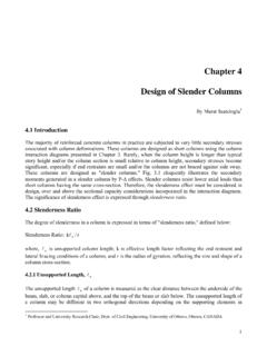
Chapter 4 Design of Slender Columns - Engineering
by.genie.uottawa.caThe critical column load, Pc (Euler buckling load) is; ()2 u 2 c k EI P l π = (4-7) Fig. 4.4 Columns in Single and Double Curvature EI in Eq. (4-7) is computed either with due considerations given to the presence of reinforcement in the section, as specified in Eq. (4-8), or approximately using Eq. (4-9). d c g s se 1 0.2E I E I EI +β + = (4-8)

Design of Columns
site.iugaza.edu.ps1 Design of Columns Introduction According to ACI Code 2.2, a structural element with a ratio of height-to-least lateral dimension exceeding three used primarily to support compressive loads is defined as column. Columns support vertical loads from the floor and roof slabs and transfer these loads to the footings.
6 INTRODUCTION TO COLUMN BUCKLING - steel-insdag.org
www.steel-insdag.orgINTRODUCTION TO COLUMN BUCKLING where λ = the slenderness ratio of the column defined by λ = λ / r The equation σcr = (π 2E)/λ2, implies that the critical stress of a column is inversely proportional to the square of the slenderness ratio of the column (see Fig. 4).
Chapter 9: Column Analysis and Design
academic.csuohio.eduThe critical buckling load can be determined by the following equation. P critical = π 2EI min /L 2 where P critical = critical axial load that causes buckling in the column (pounds or kips) E = modulus of elasticity of the column material (psi or ksi) I min = smallest moment of inertia of the column cross-section (in 2) (Most sections have I ...

05 Eurocodes Steel Workshop SIMOES
eurocodes.jrc.ec.europa.euColumn Buckling Flexural buckling is in general the buckling mode, which govern the design of a member in pure compression. For this mode in a pinned column, the elastic critical load N cr, defined as the maximum load supported by the column, free from any type of imperfections, is given by the well known Euler’s formula: E I – Bending ...

Buckling - Other End Conditions
wp.optics.arizona.eduBuckling (Columns With Other End Conditions): However, in many engineering problems we are faced with columns with other end conditions. The first condition we would like to consider is a column with one fixed end and one free (unguided) end. By observation we see that this is identical to a pinned end column with a length of 2L.