Transcription of 8 Flat Plate Analysis - Rice University
1 Copyright 2009. All rights reserved. 139 8 flat plate analysis Introduction A flat Plate is generally considered to be a thin flat component that is subjected to load conditions that cause deflections transverse of the Plate . Therefore, the loads are transverse pressures, transverse forces and moment vectors lying in the plane. Those loads are resisted mainly by bending. It is assumed that in plane membrane stresses are not present and that the transverse displacements are small . Generally, small is taken to mean a deflection that is less than half the thickness of the Plate .
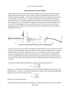
2 If the deflection is larger than that and/or membrane forces are present you have to use a non linear large deflection solution. Rectangular Plate Figure 8 1 shows some of the boundary conditions that can be applied to the edges of a Plate . A segment of a Plate can be fixed or encastred (left), simply supported (center), or mixed supported (right), or have a free edge. A simply supported condition usually means that the transverse displacement is zero on that segment but the rotation tangent to the segment is unknown. A fixed supported condition usually means that the rotation vector tangent to the segment is also zero.
3 A free edge is stress free. That is, it has no moment or transverse shear resultants acting along its length. Figure 8 1 Some typical boundary condition options on rectangular plates In this section the classic example of a simply supported Plate subjected to a uniform transverse pressure will be illustrated. Quarter symmetry will be utilized to illustrate symmetry boundary conditions for an element with displacement and rotational degrees of freedom. A short story about this case will be noted at the end. The example Plate is AISI 1020 steel with a yield stress of about 51 ksi.
4 The dimensions of the full Plate are by by inches and it is subjected to a uniform pressure of 25 psi. The total force is about 371 lb, so you expect the resultant edge reactions to be equal and opposite to that value. Since external edge effects are usually important, a finer mesh is employed along those edges. The Plate is set to be of the thin type and the study is executed. The sketch is built and converted to a planar surface with Insert Surface Planar surface. A static study is opened and the thickness set in Part Name Edit Definition Shell Definition and it is marked as a thin shell.
5 The two symmetry edges have no in plane displace normal to the edge, nor any rotation about the edge. They are invoked with Fixtures Advanced Use Reference Geometry. The two physical support edges are prevented from translation, but can have a rotation vector tangent to the edge. They are set with Fixtures Standard Immovable. Note that the immovable restraint along a planar curve has the effect of indirectly eliminating the rotation vector normal to the plane as well as the in plane rotation vector normal to the curve. The two classes of displacement restraints are shown in Figure 8 2.
6 The constant external pressure is set with External Loads Pressure Normal to, and the value is set at 25 psi. The loaded and restrained model is shown in Figure 8 3 and the mesh is in Figure 8 4. flat Plate Analysis Akin Draft Copyright 2009. All rights reserved. 140 Figure 8 2 Symmetry (left) and simple supported Plate restraints Figure 8 3 Constant normal pressure load on the Plate Figure 8 4 Refined edge mesh for a quarter symmetry rectangular Plate Post processing Displacements and rotations The Plate deflections are given in Figure 8 5.
7 The surface deflections are given as contours. The short symmetry edge deflection is graphed for more detail in the lower image. The graph starts at the outer (zero deflection) edge and goes to the maximum deflection at the Plate center (zero rotation) point. It serves to verify that the restraints were properly applied. The center point deflection can also be compared to analytic estimates [14, 17]. Here the maximum computed deflection is more than half the thickness of the Plate , therefore the small deflection assumption appears questionable. SW Simulation did not issue a warning about the change in stiffness due to perceived large deflections, but a re run will be considered later.
8 flat Plate Analysis Akin Draft Copyright 2009. All rights reserved. 141 Figure 8 5 Deflections of the quarter symmetry Plate , and its short edge Another insight to the displacement is obtained by graphing its value along lines from the supported corner point. Note in Figure 8 6 that the trend shows a reverse curvature. The deflection is restrained to zero, by an external corner force, but the trend is to a lift up at the corner. Figure 8 6 Deflection along from corner to corner (left) and to mid side Plate stresses Since plates and shells can be subjected to both bending and membrane (in plane) stresses the stress results should be checked on the top, bottom, and middle surfaces.
9 Here the membrane stress is zero (for small deflections). At a point on the Plate the stress will be in tension on one side and have an equal amount of compression on the other. That is important when the material has different strengths in tension and compression (like concrete). flat Plate Analysis Akin Draft Copyright 2009. All rights reserved. 142 The von Mises effective stress is proportional to the square root of the sum of the squares of the differences in the principal stresses, so it is always positive. The contour, and short symmetry edge, values of the von Mises stress are given in Figure 8 7.
10 Note that the peak values exceed the yield stress, and the factor of safety (FOS) with respect to material failure is less than unity. Figure 8 7 Von Mises stress in quarter symmetry Plate and its short symmetry side Figure 8 8 The principal stresses P1 and P3 on the top of the quarter symmetry Plate flat Plate Analysis Akin Draft Copyright 2009. All rights reserved. 143 Design insight The above displacement graphs suggested that the simply supported corner has a large effect on the Plate . That concept is reinforced by the plot of the material most active in the load path, plotted in Figure 8 9.