Chapter 18 Two-Port Circuits
1. Chapter 18 Two-Port Circuits. 18.1 The Terminal Equations. 18.2 The Two-Port Parameters. 18.3 Analysis of the Terminated Two-Port Circuit . 18.4 Interconnected Two-Port Circuits
Download Chapter 18 Two-Port Circuits

Information
Domain:
Source:
Link to this page:
Documents from same domain

電力電子元件簡介 - 清華大學電機系-NTHUEE
www.ee.nthu.edu.twPage 3 功功率半率半導導體元件體元件之之控制控制特性特性 (1) Uncontrolled turn-on and off: (diode) (2) Controlled turn-on and uncontrolled turn-off: (SCR)

切換式(開關式)磁阻馬達之驅動 控制與應岦
www.ee.nthu.edu.tw2 3 3 AC source +-Inverter Vdc AC motor VVVF 3 voltage Rectifier or SMR φ φ EC Load Switching control Command Controller Current feedback Velocity and/or position feedback

띌뒹ꓹ꒧껈---- - ee.nthu.edu.tw
www.ee.nthu.edu.twOutlines • 륱ꑬ꒸ꗳ꙰꛳ꑵꝀ? • ꒰믲걏ꕢ뻉엩? • PN곉궱 • CMOS꒸ꗳ슲꒶ • ꕢ뻉엩뭳땻슲꒶ • ꣤ꕌꖼ꣓ꪺ땯깩 • 뙩ꑊꕢ뻉엩믢냬삳ꚳ꒰믲럇돆?
Chapter 8 Natural and Step Responses of RLC Circuits
www.ee.nthu.edu.tw1 Chapter 8 Natural and Step Responses of RLC Circuits 8.1-2 The Natural Response of a Parallel RLC Circuit. 8.3 The Step Response of a Parallel . RLC . Circuit
Chapter 13 The Laplace Transform in Circuit Analysis
www.ee.nthu.edu.tw1. Chapter 13 The Laplace Transform in Circuit Analysis. 13.1 Circuit Elements in the s Domain. 13.2-3 Circuit Analysis in the s Domain. 13.4-5 The Transfer Function and Natural Response
電力電子元件簡介 - ee.nthu.edu.tw
www.ee.nthu.edu.twPage 2 常用功率半導體元件之額定(表二) Voltage/current ratings Switching frequency (speed) Switching time On-state resistance (or on-state voltage/current)

Lecture 8: Mechanical Vibration
www.ee.nthu.edu.tw1 ENE 5400 , Spring 2004 1 Lecture 8: Mechanical Vibration Discrete systems Energy method Lumped-parameter analysis »1 d.o.f. »Multi-d.o.f. (Eigenvalue analysis)
Chapter 11 Balanced Three-Phase Circuits
www.ee.nthu.edu.twWhy a balanced three-phase circuit can be analyzed by an equivalent one-phase circuit? How to get all the unknowns (e.g. line voltage of the load) by the result of one-phase circuit analysis? Why the total instantaneous power of a balanced three-phase circuit is a constant?
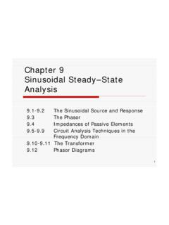
Chapter 9 Sinusoidal Steady–State Analysis
www.ee.nthu.edu.twcircuits to (1) match impedances, and (2) eliminate dc signals. Ideal transformer is used in power circuits to establish ac voltage levels. MCM is used in transformer analysis, for the currents in various coils cannot be written by inspection as functions of the node voltages.

Chapter 7 Response of First-order RL and RC Circuits
www.ee.nthu.edu.twCircuit model of a discharging RC circuit Consider the following circuit model: For t <0, C is open and biased by a voltage V g, while R 1 and R carry no current. For t >0, the capacitor voltage decreases and the energy is dissipated via R.
Related documents
Chapter 8 Natural and Step Responses of RLC Circuits
www.ee.nthu.edu.twChapter 8 Natural and Step Responses of RLC Circuits 8.1-2 The Natural Response of a Parallel RLC Circuit. 8.3 The Step Response of a Parallel . RLC . Circuit. 8.4 The Natural and Step Response of a Series . RLC . Circuit

DESIGNING COMBINATIONAL LOGIC GATES IN CMOS
bwrcs.eecs.berkeley.eduIn Figure 6.6b, the subnets (SN) for the pull-down etwork aren identified t the topA level, SN1 and SN2 are in parallel so in the dual network, they will be in series. Since SN1 B A A B Parallel Combination Figure 6.4 NMOS logic ules r — series devices implement an AND, and parallel devices implement an OR. (a) series (b) parallel Series ...
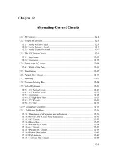
Chapter 12 Alternating-Current Circuits
web.mit.eduFigure 12.2.2 (a) Time dependence of IR (t) and VR (t) across the resistor.(b) Phasor diagram for the resistive circuit. The behavior of IR (t)and can also be represented with a phasor diagram, as shown in Figure 12.2.2(b). A phasor is a rotating vector having the following properties:

DC Electrical Circuit Analysis - MVCC
www2.mvcc.eduSubsequent chapters introduce resistance, series circuits, parallel circuits and series-parallel circuits. The text continues with chapters covering network theorems, more advanced techniques such as nodal and mesh analysis, and finally finishes with introductions to capacitors, inductors and magnetic circuits. The companion AC

Chapter 6: Inductance and Capacitance
courses.egr.uh.eduChapter 6: Inductance and Capacitance We introduce here the two remaining basic circuit elements: the inductor and the capacitor. The behavior of the inductor is based on the properties of the magnetic field generated in a coil of wire. In fact, the inductor is basically a coil of wire. Ampere’s Law: current in a coil magnetic field

A TEXTBOOK OF ELECTRICAL TECHNOLOGY
elbook.weebly.com6. The chapter on Series A.C. Circuits has been enriched with many articles such as Determination of Upper and Lower Half-power Frequencies, Value of Edge Frequencies and Relation between Resonant Power and Off-resonance Power. ... Between Series and Parallel Circuits—Relative Potential— ...
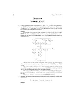
Chapter 6 PROBLEMS - #hayalinikeşfet
home.ku.edu.trThen, each of the pMOS has an output resistance equal to 6.5 k. The output resistance is equal to the series of one of these resistance with the parallel of four of the same resistnaces. Then, the minimum output resistance is 6.5 k + 6.5 k/4 = 8.125 k. 6. [E, None, 4.2] What is the logic function of circuits A and B in Figure 6.5? Which one is a

Series -Parallel Circuits
www.oakton.edu6-1: Finding RTfor Series -Parallel Resistances Overview of Series-Parallel Circuits A series-parallel circuit, or combination circuit, combines both series and parallel connections. Most electronic circuits fall into this category. Series-parallel circuits are typically used when different voltage and current values are required from the same

Electric circuits, Current, and resistance (Chapter 22 and 23)
www.physics.brocku.catraded for a 6.0 V battery. The power dissipated by the resistoris now A. 1.0 W B. 2.0 W C. 3.0 W D. 4.0 W Multiple choice Problem 1: An electric blanket has a wire that runs through the interior. A current causes energy to be dissipated in the wire, warming the blanket. A new, low-voltage electric blanket is rated to be used at 18 V.