
Chapter 6 Synchronous Sequential Circuits
In a sequential circuit, the values of the outputs depend on the past behavior of the circuit, as well ... • Asynchronous – where no clock is used . Figure 6.1. The general form of a synchronous sequential circuit. Combinational circuit Flip-flops Clock Q W Z Combinational
Download Chapter 6 Synchronous Sequential Circuits

Information
Domain:
Source:
Link to this page:
Documents from same domain

3. The Finite-Difference Time- Domain Method (FDTD)
my.ece.utah.edu3. The Finite-Difference Time-Domain Method (FDTD) The Finite-Difference Time-Domain method (FDTD) is today’s one of the most popular technique for the solution of electromagnetic problems. It has been successfully applied to an extremely wide variety of problems, such as scattering from metal objects and

MatlabTutorial : Root Locus
my.ece.utah.edu2.0 Root Locus Design Consider all positive values of k. In the limit as k -> 0, the poles of the closed-loop system are a(s) = 0 or the poles of H(s). In the limit as k -> infinity, the poles of the closed-loop system are b(s) = 0 or the zeros of H(s). No matter what we pick k to be, the closed-loop system must always have n poles, where n is the

ECE 5325/6325: Wireless Communication Systems Lecture ...
my.ece.utah.eduControl was manual, and the control channel was open for anyone to hear. In fact, users were required to be listening to the control channel. When the switching operator wanted to connect to any mobile user, they would announce the call on the control channel. If the user responded, they would tell the user which voice channel to turn to.

Solving the Generalized Poisson Equation Using the Finite ...
my.ece.utah.eduFinite-Di erence Method (FDM) James R. Nagel, nageljr@ieee.org Department of Electrical and Computer Engineering University of Utah, Salt Lake City, Utah February 15, 2012 1 Introduction The Poisson equation is a very powerful tool for modeling the behavior of …

Introduction to Bode Plot - University of Utah
my.ece.utah.edus TF sss + = ++ Simplify transfer function form: 200*20 (1)100(1) 200(20) 402020 (21)(40) (1)(1)(1)(1) 0.5400.540 ss s TF sss ssss ss ++ + === ++ ++++ Recognize: K = 100 à 20 log10(100) = 40 1 pole at the origin 1 zero at z 1 = 20 2 poles: …

Homework #3 Solution - University of Utah
my.ece.utah.eduHomework #3 Solution mirror, such as that shown at the right, all µA/V 2, L=1µm, and V A=10V. Widths reference current IREF is 20µA. What 2 and Q 3? -source operation is and ro of Q 2 and Q 3? What is the output 1 . Fall 2010 2. Find the output …

MET 382 PLC Fundamentals - Ladder fundamentals - Spr …
my.ece.utah.eduMET 382 1/14/2008 Ladder Logic Fundamentals 2 PLC Programming Languages In the United States, ladder logic is the most pppopular method used to program a PLC This course will focus primarily on ladder logic programming Other programming methods include: Function block diagrams (FBDs) 3 Structured text (ST)
Homework #1 - University of Utah
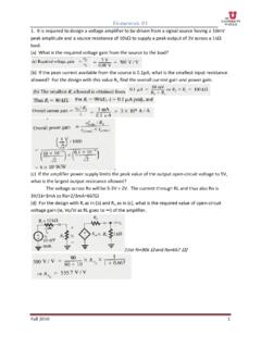
my.ece.utah.eduHomework #1 Fall 2010 3 4. For the circuit below: (a) Find the resistances looking into node 1, R1; node 2, R2; node 3, R3; and node 4, R4. (b) Find the currents I1, I 2, I 3, and I4 in terms of the input current I. (c) Find the voltage at nodes 1,2,3, and 4, that is V1, V2, V3, and V4 in terms of IR.

ECE 5520: Digital Communications Lecture Notes Fall 2009
my.ece.utah.eduA digital communication system conveys discrete-time, discrete-valued information across a physical channel. Information sources might include audio, video, text, or data. They might be continuous-time (analog) signals (audio, images) and even 1-D or 2-D. Or, they may already be digital (discrete-time, discrete-valued). Our
Related documents

CHAPTER VIII FINITE STATE MACHINES (FSM)
limsk.ece.gatech.edu• Synchronous sequential system • Behaviour depends on the inputs and outputs at discrete instants of time. • Flip-flops, registers, and latches that are enabled/controlled with a signal derived from clock form a synchronous sequential system. • Asynchronous sequential system • Behaviour depends on inputs at any instant of time.
Chapter 9 Asynchronous Sequential Logic
www.ee.ncu.edu.twAsynchronous primary difference 9-4 Synchronous vs. Asynchronous Asynchronous sequential circuits Internal states can change at any instantof time when there is a change in the input variables No clocksignal is required Have better performance but hard to design due to timing problems Synchronous sequential circuits
Simulation and Synthesis Techniques for Asynchronous …
www.sunburst-design.com• async_cmp.v - (see Example 3 in section 5.3) - this is an asynchronous pointer-comparison module that is used to generate signals that control assertion of the asynchronous “full” and “empty” status bits. This module only contains combinational comparison logic. No sequential logic is included in this module.
Synchronous Resets? Asynchronous Resets? I am so …
www.sunburst-design.comsynchronous or asynchronous resets, will every flip-flop receive a reset, how will the reset tree be laid out and buffered, how to verify timing of the reset tree, how to functionally test the reset with test scan vectors, and how to ... In Verilog, all assignments made inside the always block modeling an inferred flip-flop (sequential logic ...

Appendix I Synthesizable and Non-Synthesizable Verilog ...
link.springer.com4. Asynchronous Control signals: There should not be any internally generated asynchronous control signals 5. Do not mix the positive and negative edge triggered flip-flops 6. Avoid use of latches in the design 7. If shift registers are used then do not replace them by using scan enabled flip-flops but only ensure the enable control 8.
Chapter 5 Synchronous Sequential Logic
www.cse.iitb.ac.inthe design of asynchronous sequential circuits! Not practical for use in synchronous sequential circuits! Avoid to use latches as possible in synchronous sequential circuits to avoid design problems 5-8 SR Latch! A circuit with two cross-coupled NOR gates or two cross-coupled NAND gates! Two useful states:! S=1, R=0 " set state (Q will become ...
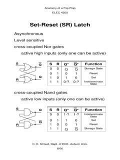
Set-Reset (SR) Latch
www.eng.auburn.eduTo verify that a sequential logic circuit will work at the specified clock frequency, fclk, we must consider the clock period, Tp, the ... Asynchronous interfaces lead to metastability (minimize the async interface & double clock data to reduce probability of metastability)
Experiment Sequential Circuits 6 PART A: FLIP FLOPS
www.iium.edu.myA sequential system can be defined in terms of its inputs and present state. That is, the next state of the sequential system ... Such circuit is also called asynchronous since the only pulse required for the operation is the clock pulse. The JK Flip Flop have the J and K inputs both tied high, which allows them