Transcription of Set-Reset (SR) Latch
1 C. E. Stroud, Dept. of ECE, Auburn of a Flip-FlopELEC 4200 Set-Reset (SR) LatchAsynchronousLevel sensitivecross-coupled Nor gatesactive high inputs (only one can be active)cross-coupled Nand gatesactive low inputs (only one can be active)SRQ+Q+Function00 QQStorage State01 0 1 Reset10 1 0 Set110-?0-?Indeterminate StateSRQ+Q+Function001-?1-?Indeterminate State01 1 0 Set10 0 1 Reset11 QQStorage StateSRQQSRQQC. E. Stroud, Dept. of ECE, Auburn of a Flip-FlopELEC 4200 Enabled Set-Reset (SR) LatchAsynchronousLevel sensitivecross-coupled Nor gatesactive high inputs (S & R cannot be active)cross-coupled Nand gatesactive low inputs (S & R cannot be active)ESRQ+Q+Function0xxQQStorage State100 QQStorage State101 0 1 Reset110 1 0 Set1110-?
2 0-?Indeterminate StateESRQ+Q+Function0001-?1-?Indetermina te State001 1 0 Set010 0 1 Reset011 QQStorage State1xxQQStorage StateSRQQESRQQEC. E. Stroud, Dept. of ECE, Auburn of a Flip-FlopELEC 4200 Transparent D LatchAsynchronousLevel sensitivecross-coupled Nor gatesactive high enable (E)cross-coupled Nand gatesactive low enable (E)EDQ+Function0xQStorage State10 0 Transparent Mode11 1 Transparent ModeEDQ+Function1xQStorage State00 0 Transparent Mode01 1 Transparent ModeDQQEQQDEC. E. Stroud, Dept. of ECE, Auburn of a Flip-FlopELEC 4200D Flip-FlopSynchronous (also know as Master-Slave FF)Edge Triggered (data moves on clock transition) one Latch transparent - the other in storageactive low Latch followed by active high latchpositive edge triggered (rising edge of CK) active high Latch followed by active low latchnegative edge triggered (falling edge of CK) QQDCKM aster Sectionactive low latchSlave Sectionactive high latchQQDCKM aster Sectionactive high latchSlave Sectionactive low latchC.
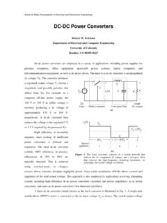
3 E. Stroud, Dept. of ECE, Auburn of a Flip-FlopELEC 4200 Timing ConsiderationsSet-up time (tsu)= minimum time input data must be valid before active edge of clockHold time (th)= minimum time input data must be held valid after active edge of clockClock-to-output delay (tco)= maximum time before output data is valid with respect to active edge of clockSet-up or Hold Time violation => metastability (Q & Q go to intermediate voltage values which are eventually resolved to an unknown state)Set-up & Hold Time violations in a vector set referred to as clock-data racestsuthDCKQtcoC. E. Stroud, Dept. of ECE, Auburn of a Flip-FlopELEC 4200 Timing ConsiderationsTo verify that a sequential logic circuit willwork at the specified clock frequency, fclk,we must consider the clock period, Tp, thepropagation delay, Pdel, of the worst casepath through the combinational logic, aswell as tsu and tco of the flip-flops suchthat the following relationship holds:For paths from flip-flop outputs to flip-flopinputs:For paths from primary inputs to flip-flopinputs:For paths from flip-flop outputs to primaryoutputs:For paths from primary inputs to primaryoutputs.
4 Timing analysis and timing simulation CADtools are typically used for this TpPdeltcotsu++ =1fclk TpPdeltsu+ =1fclk TpPdeltco+ =1fclk TpPdel =C. E. Stroud, Dept. of ECE, Auburn of a Flip-FlopELEC 4200 Good Design PracticesUse single clock, single edge synchronous design techniques as much as possibleAsynchronous interfaces lead to metastability (minimize the async interface & double clock data to reduce probability of metastability)Avoid asynchronous presets & clears on FFs (use sync presets & clears whenever possible)DO NOT construct a FF from two level sensitive latches of the same type with an inverter on the clock input to one latchDO NOT gate clocks!!!Create clock enabled FFs via a MUX to feed back current dataactivelowlatchDEQQ activelowlatchDEQQDCKQQBAD Design01 DCENCKQQA ctive high clock enable (CEN)DCENCKQQBAD DesignGOOD Desig