
Class D Amplifier Design Basics II - irf.com
• Surface mount • Dual sided cooling • Hybrid module • Multi chip module • Feedback techniques • Self-oscillating topologies • Digital domain PWM processing Higher Performance + Smaller Size + Lower Cost At The Same Time !
Download Class D Amplifier Design Basics II - irf.com

Information
Domain:
Source:
Link to this page:
Documents from same domain
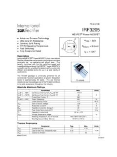
PD-91279E IRF3205 - Infineon Technologies
www.irf.comIRF3205 www.irf.com 3 Fig 1. Typical Output Characteristics Fig 2. Typical Output Characteristics Fig 3. Typical Transfer Characteristics Fig 4.
Application Note AN-1068 revA Considerations for …
www.irf.comApplication Note AN-1068 revA Considerations for Designs Using Radiation-Hardened Solid State Relays By Alan Tasker Table of Contents Introduction Page
IGBT reverse conduction characteristics Hard …
www.irf.comCOMPANY CONFIDENTIAL 18 IGBT reverse conduction characteristics Hard-switching and soft-switching Energy Saving Products BU July 2013

DC to AC Inverter IGBT Demo Board - Infineon …
www.irf.comWTC June 27, 2008 Eneerrggyy Saavviinngg cPPrroodduucttss DC to AC Inverter IGBT Demo Board Devices: IRGB4062DPBF (600V/24A Trench IGBT) High Side IGBTs

Data Sheet No. PD94173 revD IRU3037/IRU3037A …
www.irf.comIRU3037/IRU3037A & (PbF) www.irf.com 1 TYPICAL APPLICATION DESCRIPTION The IRU3037 controller IC is designed to provide a low cost synchronous Buck regulator for on-board DC to DC
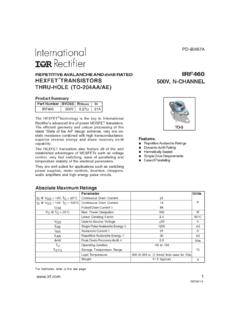
REPETITIVE AVALANCHE AND dv/dt RATED IRF460 …
www.irf.comAbsolute Maximum Ratings Parameter Units ID @ VGS = 10V, TC = 25°C Continuous Drain Current 21 ID @ VGS = 10V, TC = 100°C Continuous Drain Current 14
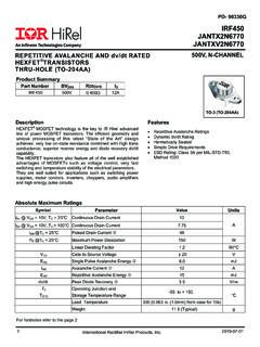
REPETITIVE AVALANCHE AND dv/dt RATED IRF450 …
www.irf.comAbsolute Maximum Ratings Parameter Units ID @ VGS =0V, TC = 25°C Continuous Drain Current 12 ID @ VGS = 0V, TC = 100°C Continuous Drain Current 7.75

Designing Practical High Performance Class D Audio …
www.irf.comwww.irf.com Contents • Class D Amplifier Introduction • The latest Digital Audio MOSFET, DirectFET® MOSFET • Designing Dead-time and Overload Protection with Digital Audio Gate
HIGH POWER, HIGH CURRENT OPERATIONAL …
www.irf.com3.4 - 41 3.4 8-Pin, TO-3 And DIP, 10 Amp Monolithic Power Operational Amplifier 4 11 R1 Supersedes 2 05 R0 HIGH POWER, HIGH CURRENT OPERATIONAL AMPLIFIER
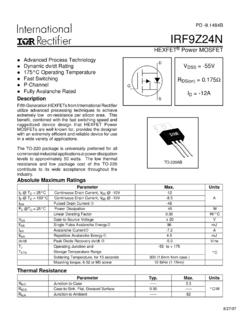
Irf9z24n - Infineon Technologies
www.irf.comIRF9Z24N Parameter Min. Typ. Max. Units Conditions IS Continuous Source Current MOSFET symbol (Body Diode) ––– ––– showing the ISM Pulsed Source Current …
Related documents

整流ダイオード製品カタログ
www.mtinc.jpsurface mount super fast schottky barrier glass passivated fast recovery glass passivated general purpose high voltage bridge (general purpose) (fast recovery) (high efficiency) (schottky barrier) (smd bridgz) general purpose fast recovery high efficiency introduction about goodwork contents symbols with explanations packing ...

MBRS340 - Schottky Rectifier
www.farnell.comSchottky Rectifier Features • Compact Surface Mount with J-bend Leads (SMC) • 3.0 W Power Dissipation Package • 3.0 A, Forward Voltage less than 500 mV Ordering Information Absolute Maximum Ratings Stresses exceeding the absolute maximum ratings may damage the device. The device may not function or be opera-

DS150i/DS151i Installation Guide Request-to-Exit PIR …
resources-boschsecurity-cdn.azureedge.netMount the detector on the ceiling, wall, or door frame. The detector can be surface mounted or mounted to a keyswitch plate with a "D" size hole. The DS150i is not tall enough to completely cover a single gang box. Where aesthetics are important, mount it using the optional trimplate (TP160 or TP161). Refer to Figure 1

B520C - B560C
www.diodes.com5.0A SURFACE MOUNT SCHOTTKY BARRIER RECTIFIER Keywords: This Schottky Barrier Rectifier is designed to meet the general requirements of commercial applications. It is ideally suited for use as a: · Polarity Protection Diode · Re-Circulating Diode · Switching Diode Created Date: 7/27/2015 10:08:46 AM
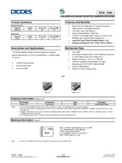
B320 - B360 - Diodes Incorporated
www.diodes.com3.0A SURFACE MOUNT SCHOTTKY BARRIER RECTIFIER Product Summary B320/B330/B340 V RRM (V) I O (A) V F max (V) I R max (mA) 20/30/40 3.0 0.5 0.1 B350/B360 V RRM (V) I O (A) V F max (V) I R max (mA) 50/60 3.0 0.7 0.1 Description and Applications This Schottky Barrier Rectifier has been designed to meet the general requirements of commercial ...

MBR120VLSF, NRVB120VLSF Schottky Power Rectifier, …
www.onsemi.comSchottky Power Rectifier, Surface Mount 1.0 A, 20 V, SOD-123 Package This device uses the Schottky Barrier principle with a large area metal−to−silicon power diode. Ideally suited for low voltage, high frequency rectification or as free wheeling and polarity protection diodes in surface mount applications where compact size and weight

MBRS140T3 - Surface Mount Schottky Power Rectifier
www.onsemi.comSurface Mount Schottky Power Rectifier MBRS140T3G, SBRS8140N, SBRS8140T3G Schottky Power Rectifiers employ the use of the Schottky Barrier principle in a large area metal−to−silicon power diode. State−of−the−art geometry features epitaxial construction with oxide passivation and metal overlay contact. Ideally suited for low voltage,
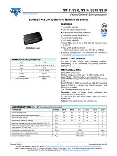
Surface-Mount Schottky Barrier Rectifier
www.vishay.comSurface-Mount Schottky Barrier Rectifier LINKS TO ADDITIONAL RESOURCES FEATURES • Low profile package • Ideal for automated placement • Guardring for overvoltage protection • Low power losses, high efficiency • Low forward voltage drop • High surge capability • Meets MSL level 1, per J-STD-020, LF maximum peak of 260 °C

Surface-Mount ESD Capability Rectifier
www.vishay.comSurface-Mount ESD Capability Rectifier LINKS TO ADDITIONAL RESOURCES FEATURES • Very low profile - typical height of 0.65 mm • Ideal for automated placement • Oxide planar chip junction • Low forward voltage drop, low leakage current • ESD capability • Meets MSL level 1, per J-STD-020, LF maximum peak of 260 °C • AEC-Q101 ...