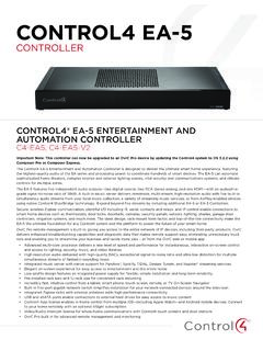
Control4 EA-5 V2 Data Sheet
USB port 1 USB 2.0 port—500mA Control IR out 8 IR out—5V 27mA max output, 1 IR blaster—front IR capture 1 IR receiver—front; 20-60 kHz Serial out 4 serial out (2 DB9 ports and 2 shared with IR out 1-2) Contact 4 contact sensors—2V-30VDC input, 12VDC 125mA maximum output Relay 4 relays—AC: 36V, 2A maximum voltage across relay;
Download Control4 EA-5 V2 Data Sheet

Information
Domain:
Source:
Link to this page:
Documents from same domain
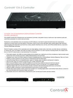
Control4® EA-3 Controller
www.control4.comControl4® EA-3 Controller The versatile Control4 EA-3 Entertainment and Automation Controller is the perfect fusion of multi-room, high-resolution audio and
Wireless Thermostat Installation Guide - Control4
www.control4.comSupported Model CCZ-T1-W Wireless Thermostat - White WARNING! Install in accordance with all national and local electrical codes. WARNING! This product is not intended for use with line-voltage baseboard heaters.

Composer HE Getting Started Guide - Control4
www.control4.comComposer HE 2.9.0 Getting Started Guide Legal notices . 2. Legal notices . Control4 disclaimer . Control4 ® makes no representations or warranties with respect to this publication, and specifically disclaims any express or implied

SR-260 System Remote Control Data Sheet
www.control4.comControl4® System Remote Control SR-260 Control4 System Remote Control SR-260 (C4-SR260, C4-SR260-I) The Control4 SR-260 and SR-260-I remotes are …
Control4 System Quick Start Guide
www.control4.comUse a dimmer 1 To use a dimmer, press and hold the top of the dimmer to slowly brighten the light, and press and hold the bottom to slowly dim it That’s all there is to it! 2 You can also use it like an on/off switch, if you’d like Press and release the top of the dimmer to ramp the light up to full brightness Press and release
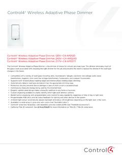
Wireless Adaptive Phase Dimmer Data Sheet
www.control4.comControl4® Wireless Adaptive Phase Dimmer The Control4® Wireless Adaptive Phase Dimmer is the dimmer of choice for virtually any load type. This dimmer eliminates much of the guess-work associated with choosing the right dimmer for the job and prevents the need to replace the dimmer if the load type changes in the future.

CONTROL4® CHIME VIDEO DOORBELL
www.control4.comChime is the first video doorbell designed for the Control4 smart home. Chime allows homeowners to see and talk to visitors while controlling the most important smart home features. Customers can see and hear who’s at the door through the Control4 mobile app or touchscreen, and a 5MP camera with a 180-degree

Control4® Wireless Switch
www.control4.comControl4® Wireless Switch The Control4® Wireless Switch provides on/off control for a variety of load types. With its robust relay and high amperage rating, the Switch can handle even high in-rush loads such as fountain pumps or large banks of fluorescent lights. It can even be used to switch wall outlets.
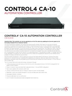
CONTROL4 CA-10
www.control4.com• 4× the processing power and memory of the EA-5 to control thousands of devices—the CA-10 is designed for the largest Control4 systems • Project is stored on dual solid-state, field-replaceable drives in mirrored RAID configuration • Dual power supplies with automatic switch-over
DUAL-WAN GIGABIT VPN ROUTER USER INTERFACE MANUAL
www.control4.comUser Interface Manual About this Manual About this Manual This manual provides installers and end users with current information regarding the installation, setup, use, and maintenance of the product. The symbols below identify important information: Pro Tip – Pro tips provide extra value, utility, or ease of use. Pro tips may also link to extra
Related documents

LT3045-1: 20V, 500mA, Ultralow Noise, - Analog Devices
www.analog.comOutput RMS Noise (Notes 4, 8) ILOAD = 500mA, BW = 10Hz to 100kHz, COUT = 10µF, CSET = 0.47µF, VOUT = 3.3V ILOAD = 500mA, BW = 10Hz to 100kHz, COUT = 10µF, CSET = 4.7µF, 1.3V ≤ VOUT ≤ 15V ILOAD = 500mA, BW = 10Hz to 100kHz, COUT = 10µF, CSET = 4.7µF, 0V ≤ VOUT < 1.3V 2.5 0.8 1.8 µVRMS µVRMS µVRMS Reference Current RMS Output Noise ...
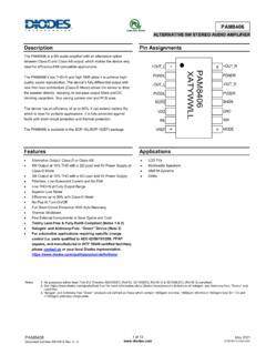
ALTERNATIVE 5W STEREO AUDIO AMPLIFIER - Diodes …
www.diodes.com• Alternative Output: Class -D or Class-AB • 5W Output at 10% THD with a 2Ω Load and 5V Power Supply at Class-D Mode • 3W Output at 10% THD with a 4Ω Load and 5V Power Supply • Filterless, Low Quiescent Current and No EMI • Low THD+N at Fully Output Range • Superior Low Noise • Efficiency up to 90% with Class-D Mode
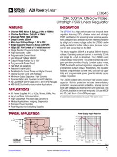
LT3045 (Rev. C) - Analog Devices
www.analog.comOutput RMS Noise (Notes 4, 8) ILOAD = 500mA, BW = 10Hz to 100kHz, COUT = 10µF, CSET = 0.47µF, VOUT = 3.3V ILOAD = 500mA, BW = 10Hz to 100kHz, COUT = 10µF, CSET = 4.7µF, 1.3V ≤ VOUT ≤ 15V ILOAD = 500mA, BW = 10Hz to 100kHz, COUT = 10µF, CSET = 4.7µF, 0V ≤ VOUT < 1.3V 2.5 0.8 1.8 µVRMS µVRMS µVRMS Reference Current RMS Output Noise ...

Building a DC-DC Step-Down (Buck) Converter Circuit Using ...
www.egr.msu.edudown to 9V output. The maximum output current that this voltage regulator can draw is 1A. However, under normal condition, the current that flows through the …
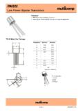
2N2222 - Farnell
www.farnell.comIC = 500mA, VCE = 10V* 35 50 75 50 100 30 300-Dynamic Characteristics Transition Frequency ft IC = 20mA, VCE = 20V f = 100MHz 250 - MHz Output Capacitance Cob VCB = 10V, IE = 0 f = 100kHz - 8 pF Input Capacitance Cib VEB = 0.5V, IC = 0 f = 100kHz - 30 Switching Characteristics Delay Time td I C = 150mA,IB1 = 15mA - 10 ns Rise Time tr VCC = 30V ...

ECUMASTER PMU-16/PMU-16DL Preliminary Manual
www.ecumaster.com+5V monitored 5V, 500mA output for powering external sensors INPUTS Page 6. Analog Inputs 16 inputs, 10 bit resolution, 0-5V (protected), with software selectable 10K Ohm pullup and pulldowns CAN Keypads 2 x Ecumaster keypads (4, 6, …

DATASHEET
datasheets.raspberrypi.comOL Output low voltageb VDD IO = 3.3V, IOL = -2mA - - TBD V V OH Output high voltageb VDD IO = 3.3V, IOH = 2mA TBD - - V I OL Output low currentc VDD IO = 3.3V, VO = 0.4V TBD - - mA I OH Output high currentc VDD IO = 3.3V, VO = 2.3V TBD - - mA R PU Pullup resistor - TBD - TBD k R PD Pulldown resistor - TBD - TBD ka a Hysteresis enabled b Default ...

BC817-16LT1 - General Purpose Transistors NPN Silicon
www.onsemi.comOutput Capacitance (VCB = 10 V, f = 1.0 MHz) Cobo − 10 − pF Product parametric performance is indicated in the Electrical Characteristics for the listed test conditions, unless otherwise noted. Product performance may not be indicated by the Electrical Characteristics if operated under different conditions.