
High-Frequency Waveform Generator - Maxim Integrated
a ±2.3V control signal, facilitating pulse-width modula-tion and the generation of sawtooth waveforms. Frequency modulation and frequency sweeping are achieved in the same way. The duty cycle and frequen-cy controls are independent. Sine, square, or triangle waveforms can be selected at the output by setting the appropriate code at two
Download High-Frequency Waveform Generator - Maxim Integrated
Information
Domain:
Source:
Link to this page:
Documents from same domain

SCAN master - Maxim Integrated
datasheets.maximintegrated.com0D[LP,QWHJUDWHG 5LR5REOHV 6DQ-RVH &$ 86$ Maxim cannot assume responsibility for use of any circuitry other than circuitry entirely embodied in a Maxim product.

A Channel Otpt an Controller - Maxim Integrated
datasheets.maximintegrated.comPin Description (continued) www.maximintegrated.com Maxim Integrated │7 MA31790 6-Channel PWM-utput Fan RPM Controller PIN NAME FUNCTION 9 TACH6

DS2401 Silicon Serial Number - Maxim Integrated
datasheets.maximintegrated.comThis command allows the bus master to read the DS2401-bit family code, unique 48bit serial ’s 8 - number, and 8bit CRC. This command can only be used if there is a single DS2401 on the bus.

Not Recommended for New Designs - Maxim …
datasheets.maximintegrated.comIt is not recommended for new designs. ... compatible with the industry-standard LT1001. ... Precision Operational Amplifier

DS1558 Watchdog Clock with NV RAM Control
datasheets.maximintegrated.comS1 s n, year 2000-compliant (Y2KC), real-time clock/calendar with an RTC alarm, watchdog timer, power-on reset, battery monitor, and NV SRAM controller.

±15kV ESD-Protected, Slew-Rate-Limited, Low …
datasheets.maximintegrated.com±15kV ESD-Protected, Slew-Rate-Limited, Low-Power, RS-485/RS-422 Transceivers SWITCHING CHARACTERISTICS—MAX481E/MAX485E, MAX490E/MAX491E, …

MAX13487E/MAX13488E Half-Duplex RS-485-/RS …
datasheets.maximintegrated.comMAX13487E/MAX13488E Half-Duplex RS-485-/RS-422-Compatible Transceiver with AutoDirection Control www.maximintegrated.com Maxim Integrated | 2 Absolute Maximum Ratings

+12V, 30mA Flash Memory Programming Supply …
datasheets.maximintegrated.comMAX662A _____Detailed Description Operating Principle The MAX662A provides a regulated 12V output voltage at 30mA from a 5V ±5% power supply, making it ideal for flash EEPROM programming applications.

MA1454 Precision Sensor Signal Conditioner with ...
datasheets.maximintegrated.comMA1454 Precision Sensor Signal Conditioner with Overvoltage Protection ˜˜ 19-5945 Rev 0; 6/11 General Description The MAX1454 is a highly integrated analog sensor

M14 Six-Channel Digital Isolator - Maxim Integrated
datasheets.maximintegrated.comMA14850 Six-Channel Digital Isolator Maxim Integrated 6 INSULATION AND SAFETY CHARACTERISTICS Note 2: All units are production tested at TA = +25°C. Specifications over temperature are guaranteed by design.
Related documents
A-Law and mu-Law Companding Implementations Using the ...
www.ti.comfor small amplitude signals consisting of unvoiced phonemes. Concurrently, the telephone system must provide for transmission of a wide range of signal amplitudes, due to the occasional occurrence of high energy voiced phonemes. The accomplishment of these concurrent tasks, within a limited bandwidth, may be achieved via Pulse Code Modulation and

LM555 Timer datasheet (Rev. D) - Texas Instruments
www.ti.comLM555 www.ti.com SNAS548D –FEBRUARY 2000–REVISED JANUARY 2015 6.5 Electrical Characteristics (TA = 25°C, VCC = 5 V to 15 V, unless otherwise specified)(1)(2) PARAMETER TEST CONDITIONS MIN TYP MAX UNIT Supply Voltage 4.5 16 V Supply Current VCC = 5 V, RL = ∞ 3 6 V mA CC = 15 V, RL = ∞ 10 15 (Low State) (3) Timing Error, Monostable

CHAPTER 2 SINGLE PHASE PULSE WIDTH MODULATED …
www.tntech.edu2.2.1 Pulse Width Modulation Control The fundamental magnitude of the output voltage from an inverter can be controlled to be constant by exercising control within the inverter itself that is no external control circuitry is required. The most efficient method of doing this is by Pulse Width Modulation (PWM) control used within the inverter.
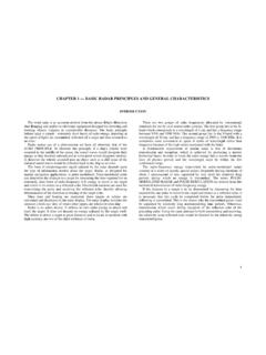
CHAPTER 1 — BASIC RADAR PRINCIPLES AND GENERAL …
msi.nga.milThe terms PULSE-MODULATED RADAR and PULSE MODULATION are derived from this method of transmission of radio-frequency energy. If the distance to a target is to be determined by measuring the time required for one pulse to travel to the target and return as a reflected echo, it is necessary that this cycle be completed before the pulse immediately

Analog vs. Digital Transmission - WPI
web.cs.wpi.eduCan actually transmit analog data in a similar manner with amplitude-, phase- and frequency-modulated waves. Stallings Fig 4.20. Two reasons: Transmission media may need to use a higher frequency than that used by the data (such as voice) Modulation permits frequency-division multiplexing. CS 513 4 week2-physcont.tex
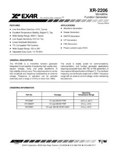
XR-2206 - SparkFun Electronics
www.sparkfun.comAmplitude Modulation Input Impedance 50 100 50 100 k Modulation Range 100 100 % Carrier Suppression 55 55 dB Linearity 2 2 % For 95% modulation Square-Wave Output Amplitude 12 12 Vp-p Measured at Pin 11. Rise Time 250 250 ns CL = 10pF Fall Time 50 50 ns CL = 10pF Saturation Voltage 0.2 0.4 0.2 0.6 V IL = 2mA Leakage Current 0.1 20 0.1 100 A VCC ...
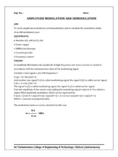
AMPLITUDE MODULATION AND DEMODULATION
svcetedu.orgIt is a type of modulation in which the frequency of the high frequency (Carrier) isvaried in accordance with the instantaneous value of the modulating signal. Consider a sine wave signal vm(t) with pulse w vm(t) = B • sin(w•t) and another sine wave vc(t) with upper pulse: vc(t) = A • …