INSTRUMENTATION AND CONTROL Module 7 Process Controls
Proportional control system c. Integral control d. Proportional plus reset control system e. Proportional plus rate control f. Proportional plus reset plus rate control IC-07 Page viii Rev. 0. Process Controls OBJECTIVES ENABLING OBJECTIVES (Cont.) 1.5 STATE the purpose of the following components of a typical control station: a. Setpoint indicator
Download INSTRUMENTATION AND CONTROL Module 7 Process Controls

Information
Domain:
Source:
Link to this page:
Documents from same domain
INSTRUMENTATION AND CONTROL Module 6 …
sites.ntc.doe.govINSTRUMENTATION AND CONTROL Module 6 Radiation Detectors. ... RADIATION DETECTION TERMINOLOGY ... Glenn F., Radiation Detection and Measurement, John Wiley and Sons, ...
ENGINEERING SYMBOLOGY, PRINTS, AND DRAWINGS Module 2 ...
sites.ntc.doe.govModule 2: Engineering Fluid Diagrams and Prints iv REFERENCES ASME Y14.5-2009, Dimensioning and Tolerancing. IEEE Std 315-1975 (Reaffirmed 1993), Graphic Symbols for Electrical and
Module 3 Reactor Theory (Nuclear Parameters) - NTC Sites
sites.ntc.doe.govreactor cooled and moderated by a subcooled liquid. 2.11 DEFINE the void coefficient of reactivity. 2.12 IDENTIFY the moderator conditions under which the void coefficient of reactivity
ENGINEERING SYMBOLOGY, PRINTS, AND DRAWINGS
sites.ntc.doe.govengineering drawing. Introduction The ability to read and understand information contained on drawings is essential to perform most engineering-related jobs. Engineering drawings are the industry's means of ... Engineering Symbology, Prints, & Drawings Intro to Print Reading .
THERMODYNAMICS, HEAT TRANSFER, AND FLUID FLOW, …
sites.ntc.doe.gov1.8 CALCULATE the fluid velocity or flow rate in a specified fluid system using the continuity equation. 1.9 DESCRIBE the characteristics and flow velocity profiles of laminar flow and turbulent flow. 1.10 DEFINE the property of viscosity. 1.11 DESCRIBE how the viscosity of a fluid varies with temperature.
THERMODYNAMICS, HEAT TRANSFER, AND FLUID FLOW …
sites.ntc.doe.gov1.25 STATE the Second Law of Thermodynamics. 1.26 Using the Second Law of Thermodynamics, DETERMINE the maximum possible efficiency of a system. 1.27 Given a thermodynamic system, CONDUCT an analysis using the Second Law of Thermodynamics. 1.28 Given a thermodynamic system, DESCRIBE the method used to determine: a. The …
MATERIAL SCIENCE Module 2 Properties of Metals
sites.ntc.doe.govTERMINAL OBJECTIVE 1.0 Without references, DESCRIBE how changes in stress, strain, and physical and chemical properties effect the materials used in a reactor plant. ENABLING OBJECTIVES 1.1 DEFINE the following terms: a. Stress b. Tensile stress

Diesel Engine Fundamentals - Energy
sites.ntc.doe.govMechanical Science Diesel Engine Fundamentals MS-01-1 DIESEL ENGINES One of the most common prime movers is the diesel engine. Before gaining an understanding of how the engine operates a basic understanding of the engine's components should be gained. This chapter reviews the major components of a generic diesel engine.
LEAD-ACID STORAGE BATTERIES - Energy
sites.ntc.doe.govLead-Acid Storage Batteries contains an introduction and sections on the following topics: Battery Components and Operation Lead-Acid Battery Types Operation and Construction Applications Sizing and Selection Maintenance Storage, Transportation, and Disposal. This text is by no means all-encompassing. ...
Module 5 Logic Diagrams - Energy
sites.ntc.doe.govequipment diagrams. The logic symbols, called gates, depict the operation/start/stop circuits of components and systems. The following two figures, which use a common facility start/stop pump circuit as an example, clearly demonstrate the reasons for learning to read logic diagrams. Figure 1 presents a schematic for a large pump, and
Related documents

Introduction to PID Control - Sharif
ee.sharif.eduThe above plot shows that the proportional controller reduced both the rise time and the steady-state error, increased the overshoot, and decreased the settling time by small amount. Proportional-Derivative control Now, let's take a look at a …

D680 Series Proportional Control Valves with Integrated ...
www.moog.comPROPORTIONAL CONTROL VALVES, D681 TO D685 SERIES The D680 Series Proportional Flow Control Valves are throttle valves for 2-, 3-, 4- and 5-way applications. These valves are suitable for electrohydraulic position, velocity, pressure or force control systems, including those with high dynamic response requirements.

Comparative study of P, PI and PID controller for speed ...
www.ijedr.orgWhile Proportional and integrative modes are also used as single control modes a derivative mode is rarely used on it’s own in control systems. Such combinations such as PI and PID controller are very often in practical systems (A) Proportional (P) Controller A P controller system is a type of linear feedback control system.
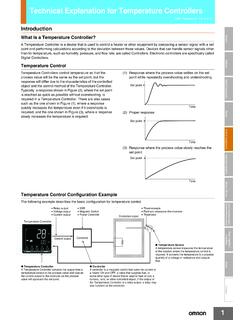
Technical Explanation for Temperature Controllers
www.ia.omron.comoperation is also called two-position control action. P action (or proportional control action) is used to output a manipulated variable (control output variable) that is proportional to the deviation in order to decrease the deviation between the process value and set point. A proportional band
PVG 32 Proportional Valves Service Parts Manual
www.grouphes.comPVG 32 Proportional Valve Service Parts Manual Installation STANDARD, OIL FLOW DIRECTION AND SETTING OF MAX. FLOW PVM TO THE RIGTH OF PVP Electrical connection Proportional activation On/off activation 25 Pin SUB-D connector with M3 screws (MIL-DTL-24308) F: Branch circuit for fault indication E: Emergency circuit braker U DC

PID Control - Waterloo Maple
www.maplesoft.comsystem with proportional control and proportional-integral control (plant transfer function: ). As can be observed, the control over the response is still limited. Proportional Derivative Control (PD) PD control is a combination of proportional and derivative control:

D660 Series Servo-Proportional Control Valves with ...
www.moog.comThe D660 Series Proportional Control Valves are of two-stage or three-stage design. The spool motion of the main stage is produced by either a single-stage or a two-stage pilot valve. Two-stage proportional valves are mainly used when low threshold and good dynamic response with small signals are
PID Control
www.cds.caltech.educontroller with proportional and derivative action is u = kpe+kd de dt = k e+Td de dt, where Td = kd/kp is the derivative time constant. The action of a controller with proportional and derivative action can be interpreted as if the control is made proportional to the predicted process output, where the prediction

Introduction to SMPS Control Techniques
www.microchip.comThe PID (Proportional Integral Derivative) control algorithm was developed in 1942 by John G. Ziegler and Nathaniel B. Nichols. The PID loop is the dominant control method for motor control, industrial process control, and plant control.