
Land Grid Array (LGA) Socket and Package Technology - Intel
handled with vacuum wand or by hand. LGA Package in Thermoformed Tray. Land Side Cover. Avoid touching. gold pads! Note: LGA packages dropped with or without the land side cover should be scrapped. Tab. Substrate. Stepped. IHS. Orientation. Notch. Capacitors. Gold Pads
Download Land Grid Array (LGA) Socket and Package Technology - Intel

Information
Domain:
Source:
Link to this page:
Documents from same domain

Intel® AMT Configuration Utility User Guide
www.intel.comIntel® AMT Configuration Utility . User Guide . Version 11.0 . Document Release Date: December 17, 2015

Microcode Revision Guide - intel.com
www.intel.comMicrocode Update Guidance Code Name Product Collection Product Names Vertical Segment CPUID Platform ID OS Update for Q2 Production Status Pre-Mitigation

U.S. Intern Relocation Guide (Including Canada)
www.intel.comFINDING HOUSING You are responsible for arranging your own housing needs, up to and including signing the lease, ordering rental furniture, paying deposits and setting up utilities.

DrMOS Specifications - Intel
www.intel.comTechnical Specifications R 7 3 Technical Specifications The feature set for the DrMOS can be divided into two major areas. They address the electrical

Intel Stratix 10
www.intel.comIntel® Stratix® 10 Intel ® StratIx® 10 Mx (DraM SySteM-In-Package) ProDuct table Notes: 1. LE counts valid in comparing across Intel FPGA devices, and …

Intel® Intel® Command Line InterfaceCommand …
www.intel.comIntel® Intel® Command Line InterfaceCommand Line InterfaceCommand Line Interface ... Intel® Command Line Interface Features and ... • Linux* command shell .

Data Sheet: MAX 3000A Programmable Logic …
www.intel.comAltera Corporation 3 MAX 3000A Programmable Logic Device Family Data Sheet The MAX 3000A architecture supports 100 % transistor-to-transistor logic

256 10 GX, MX, TX, and SX Device Family Pin …
www.intel.comIntel® Stratix® 10 GX Pin Connection Guidelines Clock and PLL Pins Note: Intel recommends that you create an Intel ® Quartus Prime design, enter your device I/O assignments, and compile the

256 10 L- and H-Tile Transceiver PHY User Guide - …
www.intel.comIntel® Stratix® 10 L- and H-Tile Transceiver PHY User Guide Subscribe Send Feedback UG-20055 | 2018.07.06 Latest document on the web: PDF | HTML

256 10 FPGA IP User Guide - intel.com
www.intel.comContents 1. External Memory Interfaces Intel ® Stratix 10 FPGA IP Introduction.....9 1.1. Intel Stratix 10 EMIF IP Design Flow.....10
Related documents
Vacuum Technology and Vacuum Design Handbook for ...
www-eng.lbl.govVacuum Technology and Vacuum Design Handbook for Accelerator Technicians This handbook is a compilation of information gathered from over 50 years of direct hands-on ... • Nitrile gloves to be used when assembling cleaned components. Other un-powdered gloves ...

真空コンポーネント部品
www.flowjoint.co.jp真空ホース(Vacuum Metal Hose) その他部材(Other Parts) ・保護キャップ(Flanges Cap)/NW用Oリング(NW O-Ring) 関連製品(Other Components) ・真空配管類(Vacuum Pipes) ガス配管(Gas Pipes) 28P 35P 34P 32P 33P

Medium Voltage Circuit Breaker Course Chapter 3.0 Student ...
www.nrc.govMedium voltage circuit breakers (air-magnetic, SF6, or vacuum type) are designed to operate electrically. This is accomplished by electrical components on the circuit breaker operating mechanism. These electrical components operate cams, wheels, rollers, and latches to charge, close and open the breaker. Electric operation:
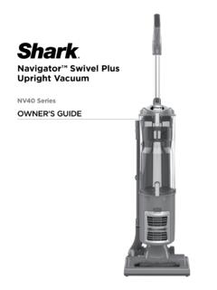
Navigator™ Swivel Plus Upright Vacuum - SharkClean.com
www.sharkclean.comLower the vacuum body onto the power nozzle. 2. Connect the nozzle hose from the vacuum body to the power nozzle. 3. Slide the handle assembly into the vacuum body. 4. Secure the handle assembly in place with included nut and bolt. 5. Insert the extension wand into the top of the nozzle hose. Store the dusting brush on the

Pressure and Vaccum Switches for Process Applications
www.sorinc.compressure and vacuum switches. Corrosive service and particular customer requirements may require optional components. Refer to How to Order section below to build a customized model number or the dedicated page to locate optional components, such as switching elements, diaphragm systems, pressure ports and accessories.