The Delay-Locked Loop
The feedback loop consists of a con-trolled delay line, a multiplier acting as a phase detector (PD), and a low-pass filter. The use of DLLs in mod-ern CMOS design evidently began with the work by Bazes in 1985 [2] and Johnson and Hudson in 1988 [3] . Basic Idea Suppose, as shown in Figure 2(a), an input clock travels on a long inter-
Download The Delay-Locked Loop

Information
Domain:
Source:
Link to this page:
Documents from same domain
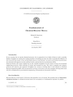
Fundamentals of Chemical Reactor Theory1 - …
www.seas.ucla.edu1 UNIVERSITY OF CALIFORNIA, LOS ANGELES Civil & Environmental Engineering Department Fundamentals of Chemical Reactor Theory Michael K. Stenstrom

Introduction to Switched-Capacitor Circuits
www.seas.ucla.eduChapter 12. Introduction to Switched-Capacitor Circuits 398 Vout Vin C1 Vout V C C1 2 AB AB in0 (a) (b) Vin VA Vin0 t0 t Vin0 C1 C2 (c) Vout Figure 12.5. Circuit of Fig. 12.4 in (a) sampling mode, (b) amplification mode.

Noise in RF Design - Engineering
www.seas.ucla.eduEE215C B. Razavi Win. 13 HO #2 17 Example Noise Figure At high frequencies, it becomes difficult to measure the input-referred noise …
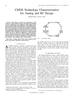
CMOS technology characterization for analog and …
www.seas.ucla.eduCMOS Technology Characterization for Analog and RF Design Behzad Razavi, Member, IEEE Abstract— The design of analog and radio-frequency (RF) circuits in CMOS technology becomes increasingly more difficult as device modeling faces new challenges in deep submicrometer processes and emerging circuit applications. The …

Analog Integrated Circuit Design - Engineering
www.seas.ucla.eduEE 215A HO#1 Fall 2014 Analog Integrated Circuit Design Instructor: Behzad Razavi 56-147D, Eng. IV
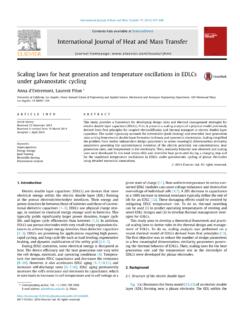
International Journal of Heat and Mass Transfer - …
www.seas.ucla.eduS;T refers to heat of mixing due to temperature gradient 638 A. d’Entremont, L. Pilon/International Journal of Heat and Mass Transfer 75 (2014) 637–649 depends on the ion concentration distribution and vice versa.

Seismic Code Requirements - Engineering
www.seas.ucla.eduBuilding Response Analysis zIn general, three types of analyses are done to design buildings subjected to earthquakes – Response History Analysis zLinear or nonlinear approach to calculate time varying responses (P, M, V, δ) – Response Spectrum Analysis zLinear approach to calculate modal responses (peak values) and combine modal responses
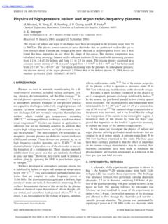
Physics of high-pressure helium and argon radio-frequency ...
www.seas.ucla.eduThe physics of helium and argon rf discharges have been investigated in the pressure range from 50 to 760 Torr. The plasma source consists of metal electrodes that are perforated to allow the gas to
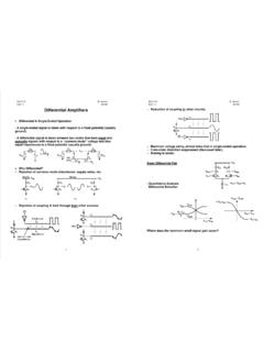
Fall 14 HO #8 - School of Engineering and Applied Science
www.seas.ucla.eduEE215A B. Razavi Fall 14 HO #8 1 Differential Amplifiers Differential & Single-Ended Operation - A single-ended signal is taken with

The Bandgap Reference - Engineering
www.seas.ucla.eduIEEE SOLID-STATE CIRCUITS MAGAZINE Summer 2016 11 First, a CMOS op amp directly driv-ing the feedback resistors must deal with gain-power-stabil-ity trade-offs.
Related documents
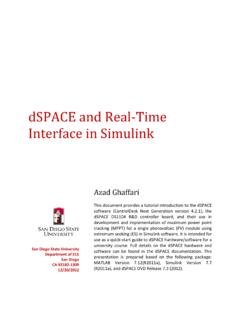
dSPACE and Real-Time Interface in Simulink
flyingv.ucsd.eduReal-Time Interface to Simulink which is a part of "RCP and HIL software" (Rapid Control Prototyping and Hardware-in the-Loop software) supports the following versions of MATLAB: R2012a, R2011b, R2011a, R2010bSP1, R2010a, R2009bSP1. 2. dSPACE Package To implement a real-time control loop using dSPACE and MATLAB we need following items. 1.

P&IDs AND LOOP DIAGRAMS - Integrated
integrated.ccloop diagram will detail the connections of pneumatics and wiring from the field device through any junction boxes or marshalling cabinet to the controller or computer interface which controls the process a single loop or a cascade loop of the process. This section will focus on the standard symbols, identification tags and terminology ...

113-2011: %DO Loop: A Simple Dynamic Programming …
support.sas.com%DO Loop – a Simple Dynamic Programming Technique Yunchao (Susan) Tian, Social & Scientific Systems, Inc., Silver Spring, MD ABSTRACT Dynamic programming is an advanced macro topic. This paper presents a simple dynamic programming technique, the %DO loop. Included topics are: 1.

Purpose of the 270/271 Health Care Eligibility Benefit ...
www.cms.govMedicare Coordination of Benefits (COB) System Interface Specifications 270/271 Health Care Eligibility Benefit Inquiry and Response . HIPAA Guidelines for Electronic Transactions Companion Document for Mandatory Reporting Non-GHP Entities . Element ID Element Name Segment ID Loop ID Valid Value(s) Format Example . NM102 . Entity Type Qualifier

Chapter 15 HUMAN MACHINE INTERFACE - eng.utoledo.edu
www.eng.utoledo.eduCh 15 Human Machine Interface 4 Fig. 15-7 A handheld thermocouple readout device with paper recording output Fig. 15-8 Several discrete controller devices for process control. Each device is capable of solving a single or multiple loops of process data executing a PID formula and controlling the output of the control loop.

I2C Serial Interface 20x4 LCD Module - HandsOn Tec
www.handsontec.comI2C Serial Interface 20x4 LCD Module This is I2C interface 20x4 LCD display module, a new high-quality 4 line 20 character LCD module with on-board contrast control adjustment, backlight and I2C communication interface. For Arduino beginners, no more cumbersome and complex LCD driver circuit connection.

AND9957 - On Board Charger (OBC) Three-phase PFC Converter
www.onsemi.comloop controls the bus voltage. Since the goal of the PFC is to guarantee 0 ° of phase delay between each phase voltage and phase current, the voltage regulation acts on the D−axes current. Q−axes current is set to be 0. D−axes represents the “ACTIVE” power branch, while Q−axes represents the “REACTIVE” power branch. Figure 5 ...
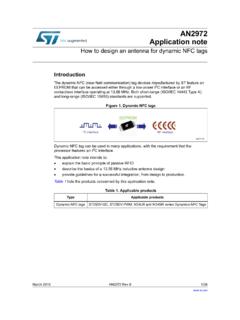
How to design an antenna for dynamic NFC tags ...
www.st.comC interface (like any serial I. 2. C EEPROM device), on the RF side, the dynamic NFC tag chip needs to be connected to an external antenna to operate. Figure 2. Dynamic NFC tag operating mode. The design of an antenna for dynamic NFC tag is based on the placement of a loop on the application PCB.