
TUTORIAL CADENCE DESIGN ENVIRONMENT
Cadence tools. A simple Operational Transconductance Amplifier (OTA) will be designed in the AMI 0.5µm CMOS technology. However, the same procedures apply to complete chip designs. 5.1. Library creation and selection of technology It is recommended that you use a library to store related cell views; e.g., use a library to hold all the
Download TUTORIAL CADENCE DESIGN ENVIRONMENT

Information
Domain:
Source:
Link to this page:
Documents from same domain
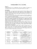
NON-DESTRUCTIVE TESTING
web.itu.edu.trNON-DESTRUCTIVE TESTING Objective To gain experience with and understanding of the types, advantages and applications of various NDT methods. To be able to choose the best NDT method for a given part.
Lecture Slides
web.itu.edu.trWelding Symbols Welding symbol standardized by American Welding Society Specifies details of weld on machine drawings Shigley’s Mechanical Engineering Design Fig. 9–4
OPERATIONS RESEARCH LECTURE NOTES
web.itu.edu.trINTRODUCTION TO OR ... “Operations Research ... [RESEARCH into (military) OPERATIONS] was coined as a suitable description of
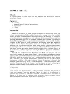
IMPACT TESTING - İTÜ
web.itu.edu.trIMPACT TESTING Objective To conduct Charpy V-notch impact test and determine the ductile-brittle transition temperature of steels. Equipment Coolants
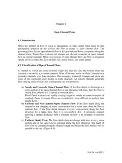
Chapter 4 Open Channel Flows - İTÜ
web.itu.edu.tr2 Prof. Dr. Atıl BULU Figure 4.1 Mathematical definition of the Uniform Steady Flow is, 0, 0 1 2 0 x y t y y y y (4.1) y0 = Normal depth d) Non-Uniform Steady Flows: The water depth changes along the channel cross- sections but does not change with time at each every cross section with time.

Lateral Earth Pressures and Retaining Walls
web.itu.edu.tr1 Lateral Earth Pressures and Retaining Walls Assistant Prof. Berrak Teymur RETAINING WALLS are usually built to hold back soil mass 1. Gravity 2. Semi-Gravity
Spark Ignition Engine Combustion - İTÜ
web.itu.edu.trProf.Dr. Cem SORUŞBAY - ITU Automotive Laboratories Engine Efficiency Thermal efficiency p ~ V diagram, compression ratio Heat losses cooling system , …
BASICS OF ELECTRICAL CIRCUITS LABORATORY …
web.itu.edu.trBASICS OF ELECTRICAL CIRCUITS LABORATORY EXPERIMENT SHEET JANUARY 2013 . 1-1 ITU Faculty of Electrical and Electronics Eng. Department of Electronics and ...
WEAVING TECHNOLOGY II - İTÜ
web.itu.edu.trTEK332E Weaving Technology II Prof. Dr. Emel Önder/ Assoc. Dr.Ömer Berkalp 3 Samples for different fabric structures Handbook of Weaving
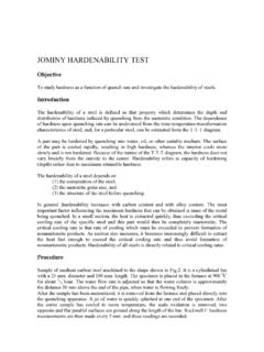
JOMINY HARDENABILITY TEST - İTÜ
web.itu.edu.trJOMINY HARDENABILITY TEST Objective To study hardness as a function of quench rate and investigate the hardenability of steels. Introduction The hardenability of a steel is defined as that property which determines the depth and
Related documents

5. CMOS Operational Amplifiers - IMS
ims.unipv.it5. CMOS Operational Amplifiers 1 Analog Design for CMOS VLSI Systems Franco Maloberti Basic op-amp The ideal operational amplifier is a voltage controlled voltage source with infinite gain, infinite input impedance and zero output impedance. The op-amp is always used in feedback configuration.
The Art of Electronics
artofelectronics.net2.2.9 Transconductance 89 2.3 Ebers–Moll model applied to basic tran-sistor circuits 90 2.3.1 Improved transistor model: transconductance amplifier 90 2.3.2 Consequences of the Ebers–Moll model: rules of thumb for transistor design 91 2.3.3 The emitter follower revisited 93 2.3.4 The common-emitter amplifier revisited 93

C2M0040120D C2M SiC MOSFET
assets.wolfspeed.comfs Transconductance 18.2 S V DS= 20 V, I DS= 40 A Fig. 7 17.2 V DS= 20 V, I DS= 40 A, T J = 150 °C C iss Input Capacitance 2440 pF V GS = 0 V V DS = 1000 V f = 1 MHz V AC = 25 mV Fig. 17,18 C oss Output Capacitance 171 C rss Reverse Transfer Capacitance 11 E oss C oss Stored Energy 89 μJ Fig 16 E ON Turn-On Switching Energy (Body Diode) 1.7 ...

IRF520 9.2A, 100V, 0.270 Ohm, N-Channel Power MOSFET
www.pcbheaven.comForward Transconductance (Note 2) gfs V DS ≥ 50V, I D = 5.6A (Figure 12) 2.7 4.1 - S Turn-On Delay Time t d(ON) V DD = 50V, I D ≈ 9.2A, R G = 18 Ω, R L = 5.5 Ω MOSFET Switching Times are Essentially Independent of Operating Temperature - 9 13 ns Rise Time t r-30 63 ns Turn-Off Delay Time t d(OFF)-18 70 ns Fall Time t f-20 59 ns Total Gate ...

Engineering Science Data Booklet Higher - SQA
www.sqa.org.ukTypical operational amplifier circuits ..... 8—10 Preface This data booklet is intended for use by candidates in examinations in Engineering Science at ... MOSFET transconductance g m = ∆I d/∆V gs. Page eight Typical operational amplifier circuits ( ) R f = feedback resistance R i = input resistance Inverting Non-inverting output voltage ...

N-Channel 30 V (D-S) MOSFET
www.vishay.comof the device at these or any other conditions beyond those in dicated in the operational sectio ns of the specifications is not implied. Exposure to absolute maximum rating conditions for extended periods may affect device reliability. SPECIFICATIONS (TJ = 25 °C, unless otherwise noted) PARAMETER SYMBOL TEST CONDITIONS MIN. TYP. MAX. UNIT Static

Automotive P-Channel 60 V (D-S) 175 °C MOSFET
www.vishay.comof the device at these or any other conditions beyond those in dicated in the operational sectio ns of the specifications is not implied. Exposure to absolute maximum rating conditions for extended periods may affect device reliability. SPECIFICATIONS (TC = 25 °C, unless otherwise noted) PARAMETER SYMBOL TEST CONDITIONS MIN. TYP. MAX. UNIT Static