Example: barber
How to Simplify the Design of an RF Remote Control Using a ...
antenna inefficiencies and wasted power. Figure 2 shows a simplified block diagram of the Si4010’s power amplifier and antenna tuning circuitry. An additional feedback loop is incorporated into the power amplifier (PA) to maintain constant output power by monitoring the voltage at the output of the PA and adjusting the PA’s current drive to
Tags:
Information
Domain:
Source:
Link to this page:
Documents from same domain
AN1107: Si5332 Power Supply Noise Rejection - Silicon Labs
www.silabs.comAN1107: Si5332 Power Supply Noise Rejection This application note showcases the power supply noise rejection (PSNR) performance of Si5332. Power supply noise are a significant problem in high performance clocking. A clock cir-cuit that is dependent on a voltage source will be affected by the noise of that source in the following ways:
Enhancing Power Supply Rejection Ratio for Low-Jitter Clocks
www.silabs.comEnhancing Power Supply Rejection Ratio for Low-Jitter Clocks . Today's electronic systems require advanced design from top to bottom. Cost and ... especially in high-power systems. Ripple as high as 100 mVp-p is common in some networking and computing applications.
DESIGN OF PRINTED TRACE DIFFERENTIAL OOP NTENNAS 1 ...
www.silabs.comalso provides a general tutorial on how to design a differential loop antenna, using a combination of design ... 2.1. Design Characteristics of Loop Antennas The following represents a brief list of some of the characteristics of loop antennas; each of these items is
High-Performance, Single-Chip …
www.silabs.comThe Si4629 supports worldwide analog AM and FM radio reception and incorporates a fully integrated decoder for the European Radio Data System (RDS) and the North
Frequency Modulation FM Tutorial - Silicon Labs
www.silabs.comFrequency Modulation (FM) Tutorial Lawrence Der, Ph.D. Silicon Laboratories Inc. Introduction Edwin H. Armstrong, known as one of the founding fathers of radio technology, invented the

AN986: BLUETOOTH® A2DP AND AVRCP PROFILES
www.silabs.comSilicon Labs TABLE OF CONTENTS 1 Introduction 4 1.1 Advanced Audio Distribution Profile 4 1.2 Audio/video Remote Control Profile 5 2 iWRAP firmware overview 6
C8051F310/1/2/3/4/5/6/7 - Silicon Labs
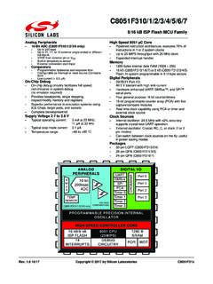
www.silabs.comC8051F310/1/2/3/4/5/6/7 Rev. 1.8 3 Table Of Contents 1. System Overview..... 17

Isolated RS232 and RS485 Expansion Board User Guide
www.silabs.comIsolated RS232 and RS485 Expansion Board User Guide The Silicon Labs Isolated RS232 and RS485 Evaluation Board is a hardware plugin card for EFM8 and EFM32 Starter Kits (STKs).
C8051F040/1/2/3/4/5/6/7 - Silicon Labs
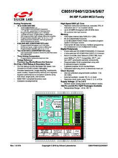
www.silabs.comC8051F040/1/2/3/4/5/6/7 Rev. 1.6 3 Table of Contents 1. System Overview..... 19

A Stroke of Genius for Smart TVs: Add Voice to Your Remote ...
www.silabs.comA Stroke of Genius for Smart TVs: Add Voice to Your Remote Control Introduction In this age of the Internet of Things (IoT), connected devices are getting smarter and smarter. We have smart phones, smart homes, smart cars, smart appliances, and even ... digitize our voice and send it over the Internet where it is processed for a response. The
Related documents
Precision, Very Low Noise, Low Input Bias Current, Wide ...
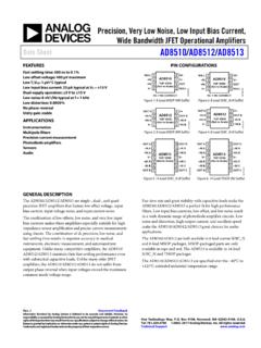
www.analog.comprecision JFET amplifiers that feature low offset voltage, input bias current, input voltage noise, and input current noise. The combination of low offsets, low noise, and very low input bias currents makes these amplifiers especially suitable for high impedance sensor amplification and precise current measurements using shunts.

THE SIMPLE HIGH-VOLTAGE REGULATOR
www.next-tube.comFor solid-state devices with rather low voltage the realization of a high-quality source does not represent the special problems. With high-voltage power supplies for tube amplifiers the states of affairs are much worse. A certain vacuum here was formed. First, there are no suitable microcircuits directly designed for work with high voltage.
Fundamentals of Optical Communications
www.cse.wustl.eduBias current 50-150 mA 100-500 mA Power output Low High Spectral Width 25-40 nm 2-5 nm Rise/Fall Time 3-20 ns 0.5-2 ns Bit Rate Lower Higher Coupling Efficiency Medium High Fiber Type Multimode Single-Mode (Generally) Failure Rate Lower Higher Safety Safe Unsafe if high power Cost Low High

Chapter 6: Transistors and Gain
physics.wm.edu1. Measure the current gain of a 2N3904 transistor using the constant current source circuit from design exercise 6-1. If you measure the collector current through the collector/load resistor for a variety of base currents (i.e. change the base resistor or the voltage applied to it), then you should be able to extract a value for β.
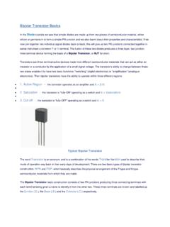
Bipolar Transistor BJT
sites.pitt.eduphase. It has a voltage gain that is always less than "1" (unity). The load resistance of the common collector transistor receives both the base and collector currents giving a large current gain (as with the common emitter configuration) therefore, providing good current amplification with very little voltage gain.

Low Noise, Precision Operational Amplifier Data Sheet OP27
www.analog.comfrequency of 2.7 Hz, and high gain (1.8 million), allow accurate high-gain amplification of low-level signals. A gain bandwidth product of 8 MHz and a 2.8 V/µs slew rate provide excellent dynamic accuracy in high speed, data-acquisition systems. A low input bias current of ±10 nA is achieved by use of a bias current cancellation circuit.
RF Power Amplifiers - QSL.net
www.qsl.netamplifiers, or the simple high impedance voltage bias used in FET PA’s. • Running the Power Amplifier in a mid-AB class condition the power gain may be 3dB higher than Class-B.

MOSFET AMPLIFIER - Learn LTSpice: A Tutorial
learn-ltspice.weebly.comLet us consider, we are using 5V supply voltage (V1). We are going to use this circuit diagram. First we have to choose the Value of R3. Let us consider V D =2.5 V, to get the maximum output swing. So, voltage drop across R3 = V1-2.5 V = 2.5V. Current Id should be less than that can be handled by the MOSFET. Let us consider the value of R3=100 Ohm.

931 Signal Conditioners - Rockwell Automation
literature.rockwellautomation.comseperately wire devices to the power supply. And the space-saving 931 Nano versions are only 6 mm wide. Critical process measurements such as temperature, pressure, flow, level, weight, speed, frequency, current or voltage in your continuous or batch production process are exposed to noise and harsh environmental

THE 37 SENSOR KIT TUTORIAL
images-eu.ssl-images-amazon.compositive pulse current 0.3~1A, reverse voltage 5V, dissipation power 90mW, working temperature range -25~+80℃, and storage temperature range between 40~100℃, the welding temperature 260 ℃) infrared tube with a closed head should be matching use,