Transcription of Bulk Metal® Foil Technology High Precision, …
1 Any questions, contact 01-Jul-2020 Bulk Metal foil Technology high precision , current sensing , Power Surface Mount ResistorBulk Metal foil Technology high precision , current sensing , Power Surface Mount Resistorwith Rated Power up to 3 W and TCR 10 ppm/ CFEATURES Temperature coefficient of resistance (TCR): 10 ppm/ C max. ( 55 C to +125 C, +25 C ref.) For tighter TCR please contact us. Power rating: 3 W Resistance tolerance: to Resistance range: 20 m to 200 m Load-life stability: to typical (70 C, 2000 h at rated power) Short-time overload: typical Power coefficient of resistance (PCR), R due to self heating : 5 ppm/W at rated power Electrostatic discharge (ESD): at least to 25 kV Solderable terminations Terminal finish available: lead (Pb)-free, tin/lead alloy Quick prototype quantities available; please contact INTRODUCTIONM odel CSM3637F is a surface mount chip resistor designed with 4 pads for Kelvin connection. Utilizing Bulk Metal foil as the resistance element, it provides enhanced characteristic capabilities resulting in superior performance when compared with other resistor technologies.
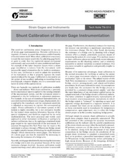
2 The unique combination of Z foil Technology along with the designed 4 pads lead frame configuration results in significant reduction of the component s sensitivity to applied power changes such as power coefficient of resistance (PCR) and thermal resistance. Note* This datasheet provides information about parts that are RoHS-compliant and/or parts that are non-RoHS-compliant. For example, parts with lead (Pb) terminations are not RoHS compliant. Please see the information/tables in this datasheet for 01-Jul-2020 Top View Bottom View Figure 1 Power Derating Curve 65 50 250255075100125150170 Ambient Temperature ( C) 100806040200 Rated Power (%)+ 70 CCSM3637 FIARZin IDV=~ BCTable 1 SpecificationsParameterValueResistance range20 m to 200 m (1)Power rating at 70 C2 W: 20 m to <50 m ; 3 W: 50 m to 200 m Maximum current (2)10 ATolerance coefficient maximum ( 55 C to +125 C, +25 C Ref.) 15 ppm/ C, R <100 m ; 10 ppm/ C(3) R 100 m Operating temperature range 65 C to +170 CMaximum working voltage(P x R)1/2 Weight (maximum) gNotes(1) Contact application engineering for values outside this range.
3 (2) Maximum current for a given resistance value is calculated using I = P/R.(3) For tighter TCR, please contact application engineering: terminal (Kelvin) design: allows for precise and accurate any questions, contact 01-Jul-2020 ABOUT CSM3637 FThe CSM3637F is a current sensing solution that was developed with a low TCR to meet demands for stable resistive product solutions in the industry. As it is critical for this resistor to reach thermal equilibrium quickly in circuits that require fast response or where the current changes swiftly, the CSM3637F is used where the emphasis is on accuracy and repeatability under stress conditions in applications requiring precision resistor performance up to 3 W. Applications as EB systems, switching power supplies, force-balanced scales all rely on current sense resistors to develop a precise voltage proportional to the 4-pad CSM3637F Bulk Metal foil surface mount resistor features an improved load-life stability of max at + 70 C for 2000 h (rated power), a TCR of 10 ppm/ C maximum from 55 C to +125 C, +25 C ref.
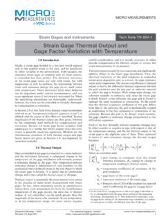
4 , and a tolerance of Key ApplicationsApplications requiring accuracy and repeatability under stress conditions such as the following: Switching and linear power supplies precision current - sensing Power management systems Feedback circuits Power amplifiers Measurement instrumentation precision instrumentation amplifiers Medical and automatic test equipment Satellites and aerospace systems Commercial and Military avionics Test and measurement equipment Electronic scalesFigure 2 Dimensions and Land Pattern in Inches (Millimeters)Kelvin ConnectionI1, I2 CurrentE1, E2 SenseCSM3637F LAND PATTERN eadcbE1E2I1I2 CSM3637F DIMENSIONSBOTTOM VIEW TOP VIEW W B A L T H TerminalsLead frameResistive elementCeramic substrateNote: Recommended stencil thickness 6 mil Tolerances ( ) ( ) ( ) ( ) ( ) ( ) ( )Land Pattern Dimensions Tolerances ( ) ( ) ( ) ( ) ( ) ( ) any questions, contact 01-Jul-2020 Table 3 Performance SpecificationsTest/ConditionMIL-PRF-4946 5B R LIMITSR esistanceValueTypical R Limits(1)Max R Limits(1)Thermal shock 65 C to +150 C, 5 cycles, 15 min at each extreme ( + )50 m to 200 m m to <50 m stability2000 h, +70 C at rated power ( + ) 100 m m to <100 m m to <50 m overload5 x rated power, 5 s ( + )20 m to 200 m temperature exposure1000 h, 170 C ( + )20 m to 200 m resistanceMIL-STD-202, method 106, 0 power, 7a and 7b not required ( + )20 m to 200 m g, 6 ms, 5 pulses ( + )20 m to 200 m to soldering heat10 s to 12 s at +260 C ( + )20 m to 200 m (1) Measurement error allowed for R limits.
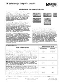
5 Figures 3 Global Part Number Information(1)NEW GLOBAL PART NUMBER:Y14750R20000B0R(preferred part number format)DENOTES PRECISIONVALUECHARACTERISTICSYR = 0 = standard9 = lead (Pb)-free1 to 999 = customPRODUCT CODERESISTANCE TOLERANCEPACKAGING1475 = CSM3637FB = = = = = waffleR = tape and reelFOR EXAMPLE: ABOVE GLOBAL ORDER Y1487 0R20000 B 0 R:TYPE: CSM3637 FVALUE: m ABSOLUTE TOLERANCE: : standard tin/leadPACKAGING: tape and reelHISTORICAL PART NUMBER STYLE: CSM3637F 0R2000 B B T (will continue to be used)CSM3637F0R2000 BBTMODELOHMIC VALUEABS. B = = = = = lead (Pb)-freeB = tin/leadT = tape and reelW = waffle packNote(1)For non-standard requests, please contact application engineering4750200RY1B00R0 Vishay precision Group, Disclaimer NoticeDocument No.: 63999 Revision: 15-Jul-2014 DisclaimerALL PRODUCTS, PRODUCT SPECIFICATIONS AND DATA ARE SUBJECT TO CHANGE WITHOUT precision Group, Inc., its affiliates, agents, and employees, and all persons acting on its or their behalf (collectively, VPG ), disclaim any and all liability for any errors, inaccuracies or incompleteness contained herein or in any other disclosure relating to any product specifications do not expand or otherwise modify VPG s terms and conditions of purchase, including but not limited to, the warranty expressed makes no warranty, representation or guarantee other than as set forth in the terms and conditions of purchase.
6 To the maximum extent permitted by applicable law, VPG disclaims (i) any and all liability arising out of the application or use of any product, (ii) any and all liability, including without limitation special, consequential or incidental damages, and (iii) any and all implied warranties, including warranties of fitness for particular purpose, non-infringement and provided in datasheets and/or specifications may vary from actual results in different applications and performance may vary over time. Statements regarding the suitability of products for certain types of applications are based on VPG s knowledge of typical requirements that are often placed on VPG products. It is the customer s responsibility to validate that a particular product with the properties described in the product specification is suitable for use in a particular application. You should ensure you have the current version of the relevant information by contacting VPG prior to performing installation or use of the product, such as on our website at license, express, implied, or otherwise, to any intellectual property rights is granted by this document, or by any conduct of products shown herein are not designed for use in life-saving or life-sustaining applications unless otherwise expressly indicated.
7 Customers using or selling VPG products not expressly indicated for use in such applications do so entirely at their own risk and agree to fully indemnify VPG for any damages arising or resulting from such use or sale. Please contact authorized VPG personnel to obtain written terms and conditions regarding products designed for such names and markings noted herein may be trademarks of their respective Vishay precision Group, Inc., 2014. All rights Disclaimer Notic