Transcription of VM2608 8-channel 16-bit Digitizer (VMIP™) VM2616
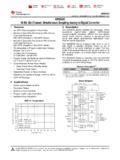
1 46 Online at 955 1894 Technology VX IThe VM2616 Digitizer provides 16 independent channels of ananalog to digital converter (ADC) with 16 bits of resolution anda sample rate of up to 100 ks/s per channel . Each channelconsists of an independent ADC combined with its owninstrumentation amplifier, providing a true differential input. Each group of four channels has a separate bank of memorywhich can be allocated to one, two, three or four allows for the most efficient use of the available module is part of the VMIP family of instruments andcan be combined with up to two other modules ( , D/A,digital I/O, time stamp, etc.) to form a high-density VXIbusinstrument. Three VM2616s can be installed in a single-wideC-size module giving 48 independent channels of input data is acquired when a conversion trigger eventoccurs from one of the four following methods: 1. Trigger source from the front panel input: This input has a 10 Volt input range, and may be programmed to trigger oneither the rising or falling edge of this signal, and at a specifiedvoltage level with a 12-bit resolution and 1% Trigger source from the VXI TTL trigger bus: Any one of theeight TTL trigger bus lines may be selected as the triggersource.
2 The unit may be programmed to trigger on either therising or falling edge of this 16-bit Digitizer (VMIP )VM261616- channel 16-bit Digitizer (VMIP )16 Independent 16-bit A/D Convertersper InstrumentEach channel has its own InstrumentationAmplifier for a True Differential OutputUp to 48 A/D Converters per VXIbus C-size SlotFlexible Triggering Capability to 40 Volt Input Ranges and up to 100kHzSampling Rate per ChannelSCPI CompatibleVXIplug&playDrivers3. Trigger upon receipt of a word serial command: When thismode is selected, the ADCs will convert when a word serialcommand is received by the instrument. 4. Trigger from one of the 16 input channels: One of the inputchannels can be selected to trigger the board. It can beprogrammed to trigger during a rising or falling edge, and alsoat a specified voltage with 12 bits of resolution and 1% ofrange accuracy. The trigger event causes all channels to convert simultaneously,and pre- and post-triggering is available for added VM2616 is designed for synchronous sampling, and allowsthe board to drive the VXIbus TTL trigger lines, enabling up to576 independent ADCs to capture data simultaneously in a 13-slot cardcage.
3 Since three VM2616s can be accommodated ona single C-size VXIbus card, three groups of 16- channel ADCseach can all be operating and triggering independently. Forexample, one can be acquiring data while another is waitingfor a Serial Message-based Data Access: In this mode,the converted data and all other functions are accessed via theVXI message-based interface. Commands are sent to querythe converted values as well as to initiate functions, such astriggering a conversion or querying each channel 's calibrationconstants. The VM2616 can return data in ASCII, and can alsoData AcquisitionProgramming and Data AccessOnline at 955 1894 Sample Rate:100 ks/s to samples per second Sample Memory:Allocated per group of four channelsCommon Mode Rejection Ratio (Typical):I/P Range10Hz 1kHz 100kHz V*110dB86dB65dB V**56dB50dB40dB V*100dB86dB50dB V**56dB50dB40dB V*90dB86dB40dB V**56dB50dB38dB* 1k source unbalance** 50 source unbalanceActiveChannels Standard Memory 512k Word Option1128k Words (131,071) 512k Words (524,287)264k Words (64,535)256k Words (262,143) Words (43,689) Words (174,761)432k Words (32,767)128k Words (131,071)Programming: Instrument.
4 SCPI compatible command set using word-serial message-based interfaceDrivers:VXIplug&playdriversUser Connector: The user connector is a standard 44-pin female high-density DSUB connector. A mating connector is provided with each unitVM261616- channel 16-bit A/D Digitizer C-size ModuleVM26088- channel 16-bit A/D Digitizer C-size Module(must be configured with a VM9000 host module)Option 2: 512 k Word Memory47 Technology VX Ireturn the maximum, minimum average, pk to pk, TRMS value,and maximum negative or positive transition between Data Access: In this mode, the data isaccessed as in any register-based VXI module, but is differentin that the local microprocessor performs additional functionsbefore passing data to the host controller. The data is thenloaded into the user-definable VXI registers for calibration constants used to correct the data values arestored in non-volatile memory. These constants aredetermined when the instrument is calibrated and can bechanged as necessary (such as during routine calibrationcycles or when the user selects a new gain setting and wishesto set the gain accurately).
5 These constants may also bequeried at any time via a word serial query and altered via aword serial command. All calibration is done using calibrationDACs to adjust the gain and offset of each channel . Thiseliminates the need for removing covers from the unit andallows for automated calibration. Resolution:16 bits, 15 bits monotonicSignal Input Type:DifferentialSignal Input Coupling:DC Signal Input Impedance: >10M , in , , 10V range. 400k differential, 200k single ended 1% in , , 40V rangeAccuracyI/P Range Common Resolution Accuracy B/W ModeI/P Range V 10 V V DC-10kHz V 40 V V DC-10kHz V 10 V V DC-20kHz V 40 V 122 V DC-20kHz V 10 V 305 V DC-20kHz V 40 V mV DC-80kHzReference Oscillator: 1 MHz derived from the VXI 10 MHz ECL clock VM2608 8-channel 16-bit Digitizer (VMIP )VM261616- channel 16-bit Digitizer (VMIP )CalibrationSpecificationsOrdering Informatio