Transcription of PRELIMINARY INFORMATION 1Gb (x8, x16) DDR2 …
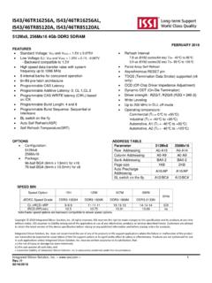
1 IS43/46DR81280, IS43/46DR16640 Integrated Silicon Solution, Inc. 1 PRELIMINARY INFORMATION MARCH 2010 1Gb (x8, x16) ddr2 sdram FEATURES Clock frequency up to 533 MHz 8 internal banks for concurrent operation 4 bit prefetch architecture Programmable CAS Latency: 3, 4, 5, 6 and 7 Programmable Additive Latency: 0, 1, 2, 3, 4, 5 and 6 Write Latency = Read Latency 1 Programmable Burst Sequence: Sequential or Interleave Programmable Burst Length: 4 and 8 Automatic and Controlled Precharge Command Power Down Mode Auto Refresh and Self Refresh Refresh Interval: s (8192 cycles/64 ms) OCD (Off Chip Driver Impedance Adjustment) ODT (On Die Termination) Weak Strength Data Output Driver Option Bidirectional differential Data Strobe (Single ended data strobe is an optional feature) On Chip DLL aligns DQ and DQs transitions with CK transitions DQS# can be disabled for single ended data strobe Read Data Strobe supported (x8 only) Differential clock inputs CK and CK# VDD and VDDQ = PASR (Partial Array Self Refresh) SSTL_18 interface tRAS lockout supported Operating temperature: Commercial (TA = 0 C to +70 C ; TC = 0 C to 85 C) Industrial (TA = 40 C to +85 C; TC = 40 C to 95 C) Automotive, A1 (TA = 40 C to +85 C; TC = 40 C to 95 C) OPTIONS Rev.
2 00A, 3/17/2010 Configuration: 128Mx8 (16M x 8 x 8 banks) 64Mx16 (8M x 16 x 8 banks) Package: 60 ball FBGA for x8 84 ball FBGA for x16 ADDRESS TABLE Parameter 128Mx8 64Mx16 Row Addressing A0 A13 A0 A12 Column Addressing A0 A9 A0 A9 Bank Addressing BA0 BA2 BA0 BA2 Precharge Addressing A10 A10 Clock Cycle Timing 37C 3D 25E 25D 19F Units Speed Grade ddr2 533C ddr2 667D ddr2 800E ddr2 800D ddr2 1066F CL tRCD tRP 4 4 4 5 5 5 6 6 6 5 5 5 7 7 7 tCK tCK (CL=3) 5 5 5 5 5 ns tCK (CL=4) ns tCK (CL=5) 3 3 3 ns tCK (CL=6) 3 ns tCK (CL=7) 3 ns Frequency (max) 266 333 400 400 533 MHz Note: The 37C device specification is shown for reference only. Copyright 2010 Integrated Silicon Solution, Inc. All rights reserved. ISSI reserves the right to make changes to this specification and its products at any time without notice.
3 ISSI assumes no liability arising out of the application or use of any INFORMATION , products or services described herein. Customers are advised to obtain the latest version of this device specification before relying on any published INFORMATION and before placing orders for products. IS43/46DR81280, IS43/46DR16640 Integrated Silicon Solution, Inc. 2 Package Ball out and Description ddr2 sdram (128Mx8) BGA Ball out (Top View) DescriptionInput clocksClock enableChip SelectCommand control pinsAddressBank AddressI/OData StrobeRedundant Data StrobeInput data maskSupply voltageGroundDQ power supplyDQ groundReference voltageDLL power supplyDLL groundOn Die Termination EnableNo connectSymbolCK, CK#CKECS#RAS#,CAS#,WE#AxBAxDQxDQS, DQS#RDQS, RDQS#DMVDDVDDLVSSDLNCVSSVDDQVSSQVREFODTN otes:1. Pins B3 and A2 have identical capacitance as pins B7 and For a read, when enabled, strobe pair RDQS & RDQS# are identical in function and timing to strobe pair DQS & DQS# and input masking function is The function of DM or RDQS/RDQS# are enabled by EMRS VDDL and VSSDL are power and ground for the DLL.
4 It is recommended that they are isolated on the device from VDD, VDDQ, VSS, and VSSQ. 1 2 3 4 5 6 7 8 9 ABCDEFGHJKLVDDDQ6 VDDQDQ4 VDDLBA2 VSSVDDRDQSVSSQDQ1 VSSQVREFCKEBA0A10A3A7A12 VSSDM/RDQSVDDQDQ3 VSSWEBA1A1A5A9 NCVSSQDQSVDDQDQ2 VSSDLRASCASA2A6A11 NCDQSVSSQDQ0 VSSQCKCKCSA0A4A8A13 VDDQDQ7 VDDQDQ5 VDDODTVDDVSSNot populated Rev. 00A, 3/17/2010 IS43/46DR81280, IS43/46DR16640 Integrated Silicon Solution, Inc. 3 ddr2 sdram (64Mx16) BGA Ball out (Top View) DescriptionInput clocksClock enableChip SelectCommand control inputsAddressBank AddressI/OUpper Byte Data StrobeLower Byte Data StrobeInput data maskSupply voltageGroundDQ power supplyDQ groundReference voltageDLL power supplyDLL groundOn Die Termination EnableNo connectVREFVDDLVSSDLNCODTVDDVSSVDDQVSSQD QxUDQS, UDQS#LDQS, LDQS#UDM, LDMRAS#,CAS#,WE#AxBAxSymbolCK, CK#CKECS#Note:VDDL and VSSDL are power and ground for the DLL.
5 It is recommended that they are isolated on the device from VDD, VDDQ, VSS, and populated Rev. 00A, 3/17/2010 IS43/46DR81280, IS43/46DR16640 Integrated Silicon Solution, Inc. 4 Rev. 00A, 3/17/2010 Functional Description Power up and Initialization ddr2 SDRAMs must be powered up and initialized in a predefined manner. Operational procedures other than those specified may result in undefined operation. Power up and Initialization Sequence The following sequence is required for Power up and Initialization. 1. Either one of the following sequence is required for Power up: A. While applying power, attempt to maintain CKE below x VDDQ and ODT1 at a LOW state (all other inputs may be undefined.) The VDD voltage ramp time must be no greater than 200 ms from when VDD ramps from 300 mV to VDD(Min); and during the VDD voltage ramp, |VDD VDDQ| V.
6 Once the ramping of the supply voltages is complete (when VDDQ crosses VDDQ(Min)), the supply voltage specifications provided in the table Recommended DC Operating Conditions ( ), prevail. VDD, VDDL and VDDQ are driven from a single power converter output, AND VTT is limited to max, AND VREF tracks VDDQ/2, VREF must be within 300mV with respect to VDDQ/2 during supply ramp time. VDDQ VREF must be met at all times B. While applying power, attempt to maintain CKE below x VDDQ and ODT1 at a LOW state (all other inputs may be undefined, voltage levels at I/Os and outputs must be less than VDDQ during voltage ramp time to avoid DRAM latch up. During the ramping of the supply voltages, VDD VDDL VDDQ must be maintained and is applicable to both AC and DC levels until the ramping of the supply voltages is complete, which is when VDDQ crosses VDDQ min.)
7 Once the ramping of the supply voltages is complete, the supply voltage specifications provided in the table Recommended DC Operating Conditions (SSTL ), prevail. Apply VDD/VDDL before or at the same time as VDDQ. VDD/VDDL voltage ramp time must be no greater 200 ms from when VDD ramps from 300 mV to VDD(Min) . Apply VDDQ before or at the same time as VTT. The VDDQ voltage ramp time from when VDD(Min) is achieved on VDD to the VDDQ(Min) is achieved on VDDQ must be no greater than 500 ms. 2. Start clock and maintain stable condition. 3. For the minimum of 200 s after stable power (VDD, VDDL, VDDQ, VREF, and VTT values are in the range of the minimum and maximum values specified in the table Recommended DC Operating Conditions (SSTL )) and stable clock (CK, CK#), then apply NOP or Deselect and assert a logic HIGH to CKE. 4. Wait minimum of 400 ns then issue a precharge all command.
8 During the 400 ns period, a NOP or Deselect command must be issued to the DRAM. 5. Issue an EMRS command to EMR(2). 6. Issue an EMRS command to EMR(3). 7. Issue EMRS to enable DLL. 8. Issue a Mode Register Set command for DLL reset. 9. Issue a precharge all command. 10. Issue 2 or more auto refresh commands. 11. Issue a MRS command with LOW to A8 to initialize device operation. ( to program operating parameters without resetting the DLL.) 12. Wait at least 200 clock cycles after step 8 and then execute OCD Calibration (Off Chip Driver impedance adjustment). If OCD calibration is not used, EMRS Default command (A9=A8=A7=HIGH) followed by EMRS OCD Calibration Mode Exit command (A9=A8=A7=LOW) must be issued with other operating parameters of EMR(1). 13. The ddr2 sdram is now ready for normal operation. Note: 1. To guarantee ODT off, VREF must be valid and a LOW level must be applied to the ODT pin.
9 IS43/46DR81280, IS43/46DR16640 Integrated Silicon Solution, Inc. 5 Initialization Sequence after Power Up Diagram tCHtCLtISCKCK#ODT~~~~~~~~~~~~CommandNOPP REALLEMRSMRSREFAnyComPREALLREFMRSEMRSEMR S400nstRPtMRDDLL EnableDLL ResetMinimum 200 CyclesOCD DefaultOCD Cal. Mode Exit~~~~tIS~~~~~~~~~~~~~~~~~~~~~~~~~~~~t MRDtRPtRFCtRFCF ollow OCD FlowcharttMRDtOIT Programming the Mode Register and Extended Mode Registers For application flexibility, burst length, burst type, CAS# latency, DLL reset function, write recovery time (WR) are user defined variables and must be programmed with a Mode Register Set (MRS) command. Additionally, DLL disable function, driver impedance, additive CAS latency, ODT (On Die Termination), single ended strobe, and OCD (off chip driver impedance adjustment) are also user defined variables and must be programmed with an Extended Mode Register Set (EMRS) command.
10 Contents of the Mode Register (MR) or Extended Mode Registers EMR[1] and EMR[2] can be altered by re executing the MRS or EMRS Commands. Even if the user chooses to modify only a subset of the MR, EMR[1], or EMR[2] variables, all variables within the addressed register must be redefined when the MRS or EMRS commands are issued. The x16 option does not have A13, so all references to this address can be ignored for this option. MRS, EMRS and Reset DLL do not affect memory array contents, which mean re initialization including those can be executed at any time after power up without affecting memory array contents. ddr2 Mode Register (MR) Setting The mode register stores the data for controlling the various operating modes of ddr2 sdram . It controls CAS# latency, burst length, burst sequence, DLL reset, tWR and active power down exit time to make ddr2 sdram useful for various applications.