Transcription of Introduction to Feedback - Designer's Guide
1 The Designer s Guide Communitydownloaded from 2016, Kenneth S. Kundert All Rights Reserved1 of 14 Version 1, 19 September 2011 This paper gives an Introduction to Feedback , opamps, and phase-locked loops with an emphasis on demonstrating how one can quickly understand the behavior of simple Feedback circuits without detailed calculations by examining the circuit and using high level updated on January 7, 2016. You can find the most recent version at Contact the author via e-mail at to make copies, either paper or electronic, of this work for personal or classroomuse is granted without fee provided that the copies are not made or distributed for profit orcommercial advantage and that the copies are complete and unmodified.
2 To distribute other-wise, to publish, to post on servers, or to distribute to lists, requires prior written to FeedbackKen KundertDesigner s Guide Consulting, to FeedbackContents2 of 14 The Designer s Guide Introduction22. An Ideal Feedback System23. Non-Inverting Amplifier44. The Virtual Short-Circuit When the Virtual Short-Circuit Principle Does Not Apply65. Voltage Follower76. Inverting Amplifier77. Transresistance Amplifier88. Integrator99. Phase-Locked Loop1010. If You Have Questions131 IntroductionFeedback is used extensively in engineering as a universal way of making thingsbehave. The basic idea is this: you have something that performs a function that youneed, but does not do it as well as you would like, so you come up with some way ofrepresenting the desired behavior, you then subtract the desired behavior from the actualbehavior and take this difference, the error, and feed it back into the input of the func-tion in such a way as to counteract and reduce the imperfection.
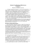
3 This is referred to anegative Feedback because you choose the sign of your Feedback to reduce the responseof your system with the idea that you are reducing the undesired behavior more than youare reducing the desired have to be careful of the sign here, otherwise you may create positive Feedback . Inthis case you are taking some of the output and feeding it back into the input in such away to make the output larger. This can explode on you. Another thing you need to be careful of is delay around the loop. It may be, if the signalyou are processing with your Feedback system is oscillatory, that the delay converts yournegative Feedback to positive Feedback . When this occurs your Feedback system beginself-sustained oscillations. Engineers study Feedback systems in great depth, and a largepart of that is so that they can avoid this type of instability, but this question of stabilitywill not be addressed in this An Ideal Feedback SystemFigure 1 shows a highly idealized Feedback system [1].
4 In this system the triangle repre-sents the original system (before Feedback is applied) and the rectangle represents thefeedback. In this case we will assume that the triangle is an amplifier with gain a, thusSo = a Se. Furthermore, f represents gain of the Feedback , thus Sf = f So. The little circlethat contains a Sigma ( ) is a summer with two inputs, a non-inverting input markedwith a plus sign (+) and the inverting input marked with a minus sign ( ), thus Se = Si Sf. Combining these relationship allows us to compute the output as a function of theinput:An Ideal Feedback SystemIntroduction to Feedback3 of 14 The Designer s Guide (1).(2)It is now helpful to define some standard terms:a is referred to as the open-loop gain,f is referred to as the Feedback factor, is referred to as the loop gain, and is referred to as the closed-loop gain of the Feedback , a is the gain of the amplifier before Feedback is applied, A is the gain after feed-back is applied, and T is the gain around the loop.
5 The loop gain T is not directly observ-able and will not be used further in this paper, but it is of central importance whenstudying the stability of the in interesting to see how this system behaves when the open-loop gain is very large:.(3)In other words, as the open loop gain of the amplifier goes to infinity, the overall gain ofthe Feedback system becomes 1/f. Thus to get a overall gain of 2, you would make thefeedback factor f = , which is an attenuator. Attenuators are generally constructed fromsimple passive components which can be made relatively precisely whereas the ampli-fier must be made of active components such as transistors and as a result the open-loopgain is often poorly controlled. By simply making the open-loop gain large you can nowcontrol the overall gain of the system precisely using a passive attenuator.
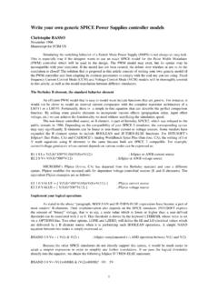
6 Correcting the gain is only one benefit from Feedback . It turns out that most of theimperfections exhibited by the amplifier are reduced by a factor of 1 + af, meaning thatthe larger the open-loop gain, the better the overall behavior becomes. Two examplesinclude linearity and bandwidth, meaning that both the linearity and bandwidth of theclosed-loop Feedback system will be better than that of the open-loop amplifier by a fac-tor of 1 + af. In effect, Feedback allows us to trade gain for 1An idealized Feedback systemSoaSeaSiSf ()aSifSo ()===Soa1af+--------------Si= +faSiSeSoSfTaf=Aa1af+--------------a1T+- -----------==A a1af+--------------a lim1f---== Introduction to FeedbackNon-Inverting Amplifier4 of 14 The Designer s Guide Non-Inverting AmplifierNow consider a practical Feedback system constructed with resistors and operationalamplifiers (opamps), both of which are shown individually in Figure 2.
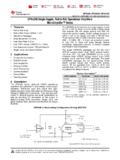
7 Here we areassuming a relatively ideal operational amplifier whose input currents are always negli-gible (approximated as being 0) and whose gain a is always large. Furthermore weassume a linear resistor with resistance consider the circuit shown in Figure 3. To derive the equations that describe thiscircuit we need to first come up with an equation that relates Vf to Vo using the charac-teristics of the resistor, then we need to calculate Vo from Vi and Vf using the characteris-tics of the opamp. The resistors are organized into a resistor string connected to resistor string acts as a voltage divider where the voltage at the output of the voltagedivider (Vf) is always a fixed fraction of the voltage at the input of the divider (Vo).
8 Thevoltage at top of the resistor string is Vo and the voltage at the bottom is 0. This causes acurrent to flow through the resistor string. The same current flows through both resistorsbecause no current flows into the negative input of the opamp. The current will equal(4).(5)Then Vf can be found by computing the voltage across R2 that results from this current:FIGURE 2 The two components used in our Feedback amplifierFIGURE 3A non-inverting Feedback amplifierpno+ Ip = 0In = 0Vo = a(Vp Vn)V = IRVIO perational AmplifierResistorR1R2 ViVoVfaVoVR1VR2+R1IR2I+==IVoR1R2+------- -------------=The Virtual Short-Circuit PrincipleIntroduction to Feedback5 of 14 The Designer s Guide (6)Thus, the gain from output to the Feedback input is:.(7)Using the equation for the opamp allows us to compute the output voltage:(8)(9)(10)Now, if we assume that a is very large:(11)Thus the output voltage has the same sign as the input voltage and is larger in magnitude(assuming the resistor values are positive).
9 Thus, this is a non-inverting amplifier, thegain of which is:(12)4 The Virtual Short-Circuit PrincipleConsider the input voltage to the opamp in Figure 3 when the open loop-gain a is verylarge:(13).(14)This implies that as a becomes large, Ve becomes small. Or more precisely,.(15)For the rest of this paper, assume that a is very large. Then the voltage at the input of theopamp can assumed to be zero (by this I mean that the voltage difference between thetwo inputs is zero, not that the voltage of both of the inputs is zero). It is as if the twoinputs are shorted. Oddly, we know from the equations that define the opamp, that thecurrent into either input is also zero. Thus, when the open loop gain is large and thefeedback is working properly then both the voltage across the input pins and the currentinto the input pins are virtually zero.
10 How are these two seemingly contradictory factsVfR2IR2R1R2+--------------------Vo= =fR2R1R2+--------------------=VoaViVf ()=VoaViR2R1R2+--------------------Vo =Voa1aR2R1R2+--------------------+------ ---------------------------ViaR1R2+()R1R 2aR2++---------------------------------- ---Vi==VoR1R2+R2--------------------Vi=A R1R2+R2--------------------=VeViVf ViR2R1R2+--------------------Vo ViR2R1R2+--------------------aVe ViafVe ====VeVi1af+--------------=Vea lim0= Introduction to FeedbackThe Virtual Short-Circuit Principle6 of 14 The Designer s Guide The Feedback always acts to reduce the opamp input voltage. Since the opamphas very high gain, the Feedback will be successful at reducing the input voltage essen-tially to zero as long as the Feedback is working.