Transcription of Lab 4.4.1: Basic VTP Configuration - Arvutiteaduse instituut
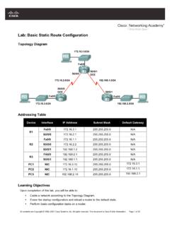
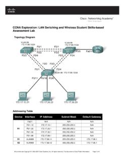
1 All contents are Copyright 1992 2007 cisco Systems, Inc. All rights reserved. This document is cisco Public Information. Page 1 of 10 Lab : Basic VTP Configuration Topology Diagram Addressing Table Device (Hostname) Interface IP Address Subnet Mask Default Gateway S1 VLAN 99 N/A S2 VLAN 99 N/A S3 VLAN 99 N/A PC1 NIC PC2 NIC PC3 NIC PC4 NIC PC5 NIC PC6 NIC CCNA Exploration LAN Switching and Wireless: VTP Lab : Basic VTP Configuration All contents are Copyright 1992 2007 cisco Systems, Inc. All rights reserved. This document is cisco Public Information. Page 2 of 10 Port Assignments (Switches 2 and 3) Ports Assignment Network Fa0/1 0/5 Trunks (Native VLAN 99) /24 Fa0/6 0/10 VLAN 30 Guest (Default) /24 Fa0/11 0/17 VLAN 10 Faculty/Staff /24 Fa0/18 0/24 VLAN 20 Students /24 Learning Objectives Upon completion of this lab, you will be able to.
2 Cable a network according to the topology diagram Erase the startup Configuration and reload a switch to the default state Perform Basic Configuration tasks on a switch Configure VLAN Trunking Protocol (VTP) on all switches Enable trunking on inter-switch connections Verify trunk Configuration Modify VTP modes and observe the impact Create VLANs on the VTP server, and distribute this VLAN information to switches in the network Explain the differences in operation between VTP transparent mode, server mode, and client mode Assign switch ports to the VLANs Save the VLAN Configuration Enable VTP pruning on the network Explain how pruning reduces unnecessary broadcast traffic on the LAN Task 1: Prepare the Network Step 1: Cable a network that is similar to the one in the topology diagram. You can use any current switch in your lab as long as it has the required interfaces shown in the topology.
3 The output shown in this lab is based on 2960 switches. Other switch types may produce different output. If you are using older switches, then some commands may be different or unavailable. You will notice in the Addressing Table that the PCs have been configured with a default gateway IP address. This would be the IP address of the local router which is not included in this lab scenario. The default gateway, the router would be needed for PCs in different VLANS to be able to communicate. This is discussed in a later chapter. Set up console connections to all three switches. Step 2: Clear any existing configurations on the switches. If necessary, refer to Lab , Appendix 1, for the procedure to clear switch configurations and VLANs. Use the show vlan command to confirm that only default VLANs exist and that all ports are assigned to VLAN 1. CCNA Exploration LAN Switching and Wireless: VTP Lab : Basic VTP Configuration All contents are Copyright 1992 2007 cisco Systems, Inc.
4 All rights reserved. This document is cisco Public Information. Page 3 of 10 S1#show vlan VLAN Name Status Ports ---- -------------------------------- --------- ----------------------------- 1 default active Fa0/1, Fa0/2, Fa0/3, Fa0/4 Fa0/5, Fa0/6, Fa0/7, Fa0/8 Fa0/9, Fa0/10, Fa0/11, Fa0/12 Fa0/13, Fa0/14, Fa0/15,Fa0/16 Fa0/17, Fa0/18, Fa0/19,Fa0/20 Fa0/21, Fa0/22, Fa0/23,Fa0/24 Gig1/1, Gig1/2 1002 fddi-default active 1003 token-ring-default active 1004 fddinet-default active 1005 trnet-default active Step 3.
5 Disable all ports by using the shutdown command. S1(config)#interface range fa0/1-24 S1(config-if-range)#shutdown S1(config-if-range)#interface range gi0/1-2 S1(config-if-range)#shutdown S2(config)#interface range fa0/1-24 S2(config-if-range)#shutdown S2(config-if-range)#interface range gi0/1-2 S2(config-if-range)#shutdown S3(config)#interface range fa0/1-24 S3(config-if-range)#shutdown S3(config-if-range)#interface range gi0/1-2 S3(config-if-range)#shutdown Step 4: Re-enable the user ports on S2 and S3. Configure the user ports in access mode. Refer to the topology diagram to determine which ports are connected to end-user devices. S2(config)#interface fa0/6 S2(config-if)#switchport mode access S2(config-if)#no shutdown S2(config-if)#interface fa0/11 S2(config-if)#switchport mode access S2(config-if)#no shutdown S2(config-if)#interface fa0/18 S2(config-if)#switchport mode access S2(config-if)#no shutdown S3(config)#interface fa0/6 S3(config-if)#switchport mode access S3(config-if)#no shutdown S3(config-if)#interface fa0/11 S3(config-if)#switchport mode access S3(config-if)#no shutdown S3(config-if)#interface fa0/18 S3(config-if)#switchport mode access S3(config-if)#no shutdown CCNA Exploration LAN Switching and Wireless: VTP Lab : Basic VTP Configuration All contents are Copyright 1992 2007 cisco Systems, Inc.
6 All rights reserved. This document is cisco Public Information. Page 4 of 10 Task 2: Perform Basic Switch Configurations Configure the S1, S2, and S3 switches according to the following guidelines and save all your configurations: Configure the switch hostname as indicated on the topology. Disable DNS lookup. Configure an EXEC mode password of class. Configure a password of cisco for console connections. Configure a password of cisco for vty connections. (Output for S1 shown) Switch>enable Switch#configure terminal Enter Configuration commands, one per line. End with CNTL/Z. Switch(config)#hostname S1 S1(config)#enable secret class S1(config)#no ip domain-lookup S1(config)#line console 0 S1(config-line)#password cisco S1(config-line)#login S1(config-line)#line vty 0 15 S1(config-line)#password cisco S1(config-line)#login S1(config-line)#end %SYS-5-CONFIG_I: Configured from console by console S1#copy running-config startup-config Destination filename [startup-config]?
7 Building [OK] Task 3: Configure the Ethernet Interfaces on the Host PCs Configure the Ethernet interfaces of PC1, PC2, PC3, PC4, PC5, and PC6 with the IP addresses and default gateways indicated in the addressing table at the beginning of the lab. Verify that PC1 can ping PC4, PC2 can ping PC5, and that PC3 can ping PC6. Task 4: Configure VTP on the Switches VTP allows the network administrator to control the instances of VLANs on the network by creating VTP domains. Within each VTP domain, one or more switches are configured as VTP servers. VLANs are then created on the VTP server and pushed to the other switches in the domain. Common VTP Configuration tasks are setting the operating mode, domain, and password. In this lab, you will be using S1 as the VTP server, with S2 and S3 configured as VTP clients or in VTP transparent mode. Step 1: Check the current VTP settings on the three switches.
8 S1#show vtp status VTP Version : 2 Configuration Revision : 0 Maximum VLANs supported locally : 255 Number of existing VLANs : 5 VTP Operating Mode : Server CCNA Exploration LAN Switching and Wireless: VTP Lab : Basic VTP Configuration All contents are Copyright 1992 2007 cisco Systems, Inc. All rights reserved. This document is cisco Public Information. Page 5 of 10 VTP Domain Name : VTP Pruning Mode : Disabled VTP V2 Mode : Disabled VTP Traps Generation : Disabled MD5 digest : 0x57 0xCD 0x40 0x65 0x63 0x59 0x47 0xBD Configuration last modified by at 0-0-00 00:00:00 Local updater ID is (no valid interface found) S2#show vtp status VTP Version : 2 Configuration Revision : 0 Maximum VLANs supported locally : 255 Number of existing VLANs : 5 VTP Operating Mode : Server VTP Domain Name : VTP Pruning Mode : Disabled VTP V2 Mode : Disabled VTP Traps Generation : Disabled MD5 digest : 0x57 0xCD 0x40 0x65 0x63 0x59 0x47 0xBD Configuration last modified by at 0-0-00 00:00.
9 00 Local updater ID is (no valid interface found) S3#show vtp status VTP Version : 2 Configuration Revision : 0 Maximum VLANs supported locally : 255 Number of existing VLANs : 5 VTP Operating Mode : Server VTP Domain Name : VTP Pruning Mode : Disabled VTP V2 Mode : Disabled VTP Traps Generation : Disabled MD5 digest : 0x57 0xCD 0x40 0x65 0x63 0x59 0x47 0xBD Configuration last modified by at 0-0-00 00:00:00 Note that all three switches are in server mode. Server mode is the default VTP mode for most Catalyst switches. Step 2: Configure the operating mode, domain name, and VTP password on all three switches. Set the VTP domain name to Lab4 and the VTP password to cisco on all three switches. Configure S1 in server mode, S2 in client mode, and S3 in transparent mode.
10 S1(config)#vtp mode server Device mode already VTP SERVER. S1(config)#vtp domain Lab4 Changing VTP domain name from NULL to Lab4 S1(config)#vtp password cisco Setting device VLAN database password to cisco S1(config)#end S2(config)#vtp mode client Setting device to VTP CLIENT mode S2(config)#vtp domain Lab4 Changing VTP domain name from NULL to Lab4 S2(config)#vtp password cisco CCNA Exploration LAN Switching and Wireless: VTP Lab : Basic VTP Configuration All contents are Copyright 1992 2007 cisco Systems, Inc. All rights reserved. This document is cisco Public Information. Page 6 of 10 Setting device VLAN database password to cisco S2(config)#end S3(config)#vtp mode transparent Setting device to VTP TRANSPARENT mode. S3(config)#vtp domain Lab4 Changing VTP domain name from NULL to Lab4 S3(config)#vtp password cisco Setting device VLAN database password to cisco S3(config)#end Note: The VTP domain name can be learned by a client switch from a server switch, but only if the client switch domain is in the null state.