Transcription of Feedback Loop Design of an LLC Resonant Power …
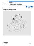
1 ApplicationReportSLUA582A October2010 ,aslongasthemodulatorBodeplotsareobtaine d,thefrequencydomainpolesandzerosinthefe edbackloopcompensationcanbeanalyticallyd etermined,thenfine-tunedwitha necessaryaspartoffeedbackloopdesignbecau sea practicalsmall-signalmodelis ' ,theUCC25600 EVM-341, canbefoundintheproductdatasheetandtheeva luationmoduleuser s guide,respectively; (w) andGc(w)..33 InitialGm(w) (w)..75 DesignofGc(w).. October2010 RevisedNovember2010 FeedbackLoopDesignofanLLCR esonantPowerConverterSubmitDocumentation Feedback 2010,TexasInstrumentsIncorporatedC1 CrR1R3R4Q1D1D2 LrLmQ2R5R2 VSCRSCRXVrefVoutVrVinVSUCC25600 GateDrivefControlSW-FrequencyModulatorT1 n:1:1 FBOFBRFBCCTRG (s)cG (s)mRTG (s) =lp= G (s) G (s)cm V (s)V (s)outrG ( ) =lpw= G ( ) G ( )cmw wV ( )V ( ) :ForcompletedetailsonthedesignofanLLCres onantpowerconverter,therecommendedrefere nceis SEM1900 Topic3, showsa TypicalLLCR esonantHalf-BridgeConverterThisdiagramco nsistsoftwoblocks.
2 Themodulatorandthecompensator,expressedi n therespectivetransferfunctionsofGm(s)and Gc(s),orGm(jw) andGc(jw). InFigure1, theredoutlinedefinestheGm(s)transferfunc tion,andtheblueoutlinedefinestheGc(s) (w)andGc(w)canbeusedtoexpressGm(jw) andGc(jw) respectivelyin shorthand,wherej= 1 (s),orGlp(w), is expressedasEquation1.(1)orasEquation2:(2 )2 FeedbackLoopDesignofanLLCR esonantPowerConverterSLUA582A October2010 RevisedNovember2010 SubmitDocumentationFeedback 2010,TexasInstrumentsIncorporatedG ( ) =mwFBOFBCG ( ) =cwFBCFBRG ( ) =lpwFBOFBRC1 CrR1R3R4Q1D1D2 LrLmQ2R5R2 VSCRSCRXVrefVoutVrVinVSUCC25600 GateDrivefControlSW-FrequencyModulatorT1 n:1:1 FBOFBRFBCCTRG ( )cwG ( ) (w) andGc(w) canbemeasuredwitha frequencysweepingsignalappliedonresistor RSC, astheseequationsshow:(3)(4)Theloopgaintr ansferfunctionGlp(w) is measurableandobtainedasEquation5.
3 (5)It is obviousthatFBCcanbeassignedatdifferentlo cationsin ,it canbemovedtotheoptocouplerinputasFigure2 ,theredareaandthebluearearepresenttheGm( w) andGc(w) functions,respectively,astheydoin (w) andGc(w)Inthisposition,then,themeasuredG m(w) andGc(w) aredifferentfromthosemeasuredin is possibletodefineGm(w) andGc(w) in (w) willbethesame,regardlessofhowGm(w) andGc(w) ,weusethedefinitionasshowninFigure1 October2010 RevisedNovember2010 FeedbackLoopDesignofanLLCR esonantPowerConverterSubmitDocumentation Feedback 2010,TexasInstrumentsIncorporatedG (s) =cswI swp_opto+ 1((+ 1s1R1 C1 wI=R CTR 4R R C32 1G (s) =cjwwI jwwp_opto+ 1((+ 1=jw11jwwIR1 C1 with: R1 = 0<<wwp_optojwwIG ( ) =cw= 1=wwIjwwI|G ( )| =cw (w), Gc(w) Figure1, if weuseTypeI compensation,thenGc(w) is expressedasEquation6:(6)Wherewp_optois 2p 10kHz,althoughthevaluevarieswiththeparti cularoptocouplerin theoptocouplercurrenttransferratio;thean gularfrequencywIis thegainofthefrequencydomainpoleatorigin. ))))
4 Andtherefore,wearriveat:(7)Theangularfre quencywIis the0-dBcrossoverofGc(w) whenwesetR1= 0 :(8)If welet|Gc(w)| = 1,then:(9)TocompensatetheLLCconverterfee dbackloop,Gm(w) (w) measurable,thefeedbackloopmustbestable,w hichis a circlethatwemustbreakin ,onecommontechniqueis tousea large-valuecapacitorforC1in Figure1 topushtheloopbandwidth(thatis,thegaincro ssoverfrequency)lowenoughin workableandallowsustoobtaininitialGm(w) ,though,wemaybeconfusedabouthowlargea capacitoris adequatefora specificapplicationin ordertomakeastableGm(w) anestimatedC1valueis notsufficient,wehavea potentialriskthattheresultingloopmaynotb establetomeasureGm(w)
5 , ,weproposea morereliableapproachthatcombineswiththep racticeofusinganinitiallowbandwidthmeasu rementfroma largevalueC1. Asweknow,tomaintainoutputvoltageregulati onin anLLCresonantconverter, theinputvoltageis notsufficient, ,evenif outputregulationis notachieved,theconverteris stable,andthisstabilityis ,benchtestsshowa Gm(w) cancontinuetobemeasuredin (w) is notexactlythesameasthatobtainedfromanope rationwhentheoutputcomesintoregulation,i t is , October2010 RevisedNovember2010 SubmitDocumentationFeedback 2010,TexasInstrumentsIncorporatedwI=R CTR 4R R C32 ,wefirstmustmakesurethatallothersegments oftheconverterworkproperly, usuallycalledanopen-looptest, (w) inthisway.
6 Low,thecontrollerin thefeedbackloopwillgeneratethemaximumgai ntoraisetheoutputvoltageasmuchtothepoint ofregulationasit can. Wethencontinuetoincreasetheinputvoltageu ntiltheoutputvoltageis closetotheregulation(within10%).Atthatpo int, Then,weapplya (w) 1%incrementsifGm(w) , ,weofferanexampletoshowhowtomakethistype ofinitialGm(w) measurement,thenhowtodesignthesubsequent feedbacklooponcethemeasurementis Figure1. Completeschematicsforthisdevicearefoundi n : Inputvoltage:375 VDCto405 VDC Outputpower(rated):300W Outputvoltage:12 VDC Outputcurrent(rated):25A Outputvoltagelineregulation(withIO= ): 1% Outputvoltageloadregulation(atVIN= 390V): 1% Outputvoltagepeak-to-peakripple(atVIN= 390V andIO= 25A): 120mV Efficiency(atVIN= 390V andIO= 25A): 90% Switchingfrequency:70kHzto150kHzin normaloperation (w) measurement; :(10)C1is onlytheparameterwemustdetermineinitially fora stableGm(w) ,CTRis fixedafteranoptocoupleris , , and1mF.
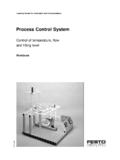
7 Thisrangeis C1isoutsidethesevalues, ,weuseC1= (notethatit doesnotmakemuchdifferencetouseC1= ). (w) Step1,theoutputvoltageregulationis 12V weusea voltagemuchlowerthan375V,theoutputvoltag eis goodruleofthumbis touseaninputvoltagelowenoughtokeeptheout putvoltageoutofregulation,butcloseto5 SLUA582A October2010 RevisedNovember2010 FeedbackLoopDesignofanLLCR esonantPowerConverterSubmitDocumentation Feedback 2010,TexasInstrumentsIncorporated6040200 204060---Gain (dB)101001 k10 k100 k1 M18012060060120180---Phase (degrees)UCC25600 EVM MODULATOR PLOT (285 V, 1 A)Frequency (Hz)GainPhasew pI= 102100(Hz) = rad/s -2820wI=R CTR 4R R C32 ;say,within10%.
8 It doesnot,a valueclosertoregulationmaybetested,using a 1%incrementeachtimeuntila goodmeasurementis ,whenweslowlyincreaseVINto285V withIO= 1 A,theoutputvoltageshowedtobeapproximatel y11V,whichis (w) (w) measurementis shownin (w) (w) basedonGm(w) properGc(w) ruleofthumb, weuseone-tenthofitsminimumswitchingfrequ ency,thatallowsapproximately7 mind,though,thatweareonlyatthebeginnings tagesandourprimarypurposeis (w) obtainedsofaris alsoa , ,it thatit hasa flatphaseanglecloseto0 ; thisresponsehelpstoachievethedesiredstab ilityasa 90 ,again,thistargetis onlyaninitialdesign; ,| Gm(w) | = ,wewouldneedtodesign| Gc(w) | tohave:20log(|Gc(w) |)w= 2p 100Hz= 28dBBecausethecrossoverfrequencyof100 Hzis a roughnumbertobeusedinitially,wecansimply doaquickdesignwithonlywIwhileleavingoutt hezeroofR1-C1bymakingR1= 0,suchthatthezeroofR1-C1is pushedbeyonditseffecttothe100-Hzcrossove r.
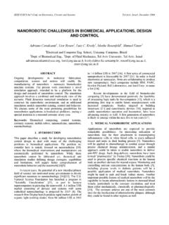
9 (11)(12)If C1= ,wecanobtainawI= ,or I= ,witha givenCTR= 120%,R4= 510 ,R2= 110k , andR3= .6 FeedbackLoopDesignofanLLCR esonantPowerConverterSLUA582A October2010 RevisedNovember2010 SubmitDocumentationFeedback 2010,TexasInstrumentsIncorporated6040200 204060---Gain (dB)101001 k10 k100 k1 M18012060060120180---Phase (degrees)UCC25600 EVM MODULATOR PLOT (TEST)Frequency (Hz)GainPhase4032241680816243240-----Gai n (dB)101001 k10 k100 k1 MPhase (degrees)GAIN OF TYPE I COMPENSATORF requency (Hz) (w).Nowweareconfidentenoughtoincreasethe inputvoltagesotheoutputis in regulation,andthenmakea stablemeasurementofGm(w).
10 ThemeasuredGm(w) is shownin Figure4, (w)Certainly,onecanmakeadditionalmeasure mentsbetween280V and390V,sayin 20-Vincrements,togainconfidencein slowincreaseoftheinputvoltagecanallowtim eforthedesignertodecidetostopif thereis (w) basedonmeasuredGm(w).Toachievethecrossov erfrequencyof7 kHzwitha minimum45 phasemargin,Gc(w) wouldneedtobedesignedtoachievetheBodeplo tresponsesshownin Figure5. Thisresultcanbeeasilyaccomplishedbyarran gingthepoleandthezeroshownin Equation6. Belowis onepossiblesetofparameterstoachievetheil lustratedBodeplots: R1= R2= R3= R4= 510 C1= CTR= 120% (w)7 SLUA582A October2010 RevisedNovember2010 FeedbackLoopDesignofanLLCR esonantPowerConverterSubmitDocumentation Feedback 2010,TexasInstrumentsIncorporated6040200 204060---Gain (dB)101001 k10 k100 k1 M18012060060120180---Phase (degrees)UCC25600 EVM LOOP PLOT (TEST)Frequency (Hz) toplugin theobtainedparametervaluestoperforma ,finetuningisnecessarytocoveralloperatin gconditionsandtoadapttotheparametersnotm odeledin theGc(w)