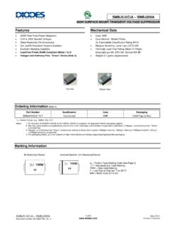
Transcription of SMAJ5.0(C)A – SMAJ200(C)A - Diodes Incorporated
1 (C)A SMAJ200(C)A Document number: DS19005 Rev. 18 - 2 1 of 6 September 2019 Diodes Incorporated (C)A SMAJ200(C)A 400W SURFACE MOUNT TRANSIENT VOLTAGE SUPPRESSOR Features 400W Peak Pulse Power Dissipation Glass Passivated Die Construction Unidirectional and Bidirectional Versions Available Excellent Clamping Capability Fast Response Time Lead-Free Finish; RoHS Compliant (Notes 1 & 2) Halogen and Antimony Free. Green Device (Note 3) An Automotive- Compliant Part is Available Under Separate Datasheet ( (C)AQ-SMAJ200(C)AQ) Mechanical Data Case: SMA Case Material: Molded Plastic. UL Flammability Classification Rating 94V-0 Moisture Sensitivity: Level 1 per J-STD-020 Terminals: Lead-Free Plating (Matte Tin Finish). Solderable per MIL-STD-202, Method 208 Polarity Indicator: Cathode Band (Bi-Directional Devices do not Have a Polarity Indicator) Weight: grams (Approximate) Ordering Information (Note 4) Part Number Compliance Case Packaging SMAJXXX(C)A-13-F Standard SMA 5000/Tape & Reel *x = Device Voltage, Example: SMAJ170A-13-F Notes: 1.
2 EU Directive 2002/95/EC (RoHS), 2011/65/EU (RoHS 2) & 2015/863/EU (RoHS 3) compliant. All applicable RoHS exemptions applied. 2. See for more information about Diodes Incorporated s definitions of Halogen- and Antimony-free, "Green" and Lead-free. 3. Halogen- and Antimony-free "Green products are defined as those which contain <900ppm bromine, <900ppm chlorine (<1500ppm total Br + Cl) and <1000ppm antimony compounds. 4. For packaging details, go to our website at Marking Information GreenTop View Bottom View xx = Product Type Marking Code (See Electrical Characteristics Table) = Manufacturers Code Marking YWW = Date Code Marking Y = Last Digit of Year (ex: 9 for 2019) WW = Week Code (01 to 53) YWW xxe3 SMA (C)A SMAJ200(C)A Document number: DS19005 Rev.
3 18 - 2 2 of 6 September 2019 Diodes Incorporated (C)A SMAJ200(C)A Maximum Ratings (@TA = +25 C unless otherwise specified.) Characteristic Symbol Value Unit Peak Pulse Power Dissipation (Non-Repetitive Current Pulse Derated above TA = +25 C) (Note 5) PPK 400 W Peak Forward Surge Current, Single Half Sine Wave Superimposed on Rated Load (Notes 5, 6 and 7) IFSM 40 A Steady State Power Dissipation @ TL = +75 C PM(AV) W Instantaneous Forward Voltage @ IPP = 35A (Notes 5, 6, and 7) VF V Notes: 5. Valid provided that terminals are kept at ambient temperature. 6. Measured with single half sine-wave. Duty cycle = 4 pulses per minute maximum. 7. Unidirectional units only. Thermal Characteristics Characteristic Symbol Value Unit Operating Temperature Range TJ -55 to +150 C Storage Temperature Range TSTG -55 to +175 C (C)A SMAJ200(C)A Document number: DS19005 Rev.
4 18 - 2 3 of 6 September 2019 Diodes Incorporated (C)A SMAJ200(C)A Electrical Characteristics (@TA = +25 C unless otherwise specified.) Part Number Add C For Bidirectional (Note 8) Reverse Standoff Voltage Breakdown Voltage VBR @ IT (Note 9) Test Current Max. Reverse Leakage @ VRWM (Note 10) Max. Clamping Voltage @ IPP Max. Peak Pulse Current IPP Marking Code VRWM (V) Min (V) Max (V) IT (mA) IR ( A) VC (V) (A) BI- UNI- (C)A 10 800 TE HE (C)A 10 800 TG HG (C)A 10 500 TK HK (C)A 10 200 TM HM (C)A 100 TP HP (C)A 50 TR HR (C)A 10 TT HT (C)A TV HV SMAJ10(C)A 10 TX HX SMAJ11(C)A 11 TZ HZ SMAJ12(C)A 12 UE IE SMAJ13(C)A 13 UG IG SMAJ14(C)A 14 UK IK SMAJ15(C)A 15 UM IM SMAJ16(C)A 16 UP IP SMAJ17(C)A 17 UR IR SMAJ18(C)A 18 UT IT SMAJ20(C)A 20 UV IV SMAJ22(C)A 22 UX IX SMAJ24(C)A 24 UZ IZ SMAJ26(C)A 26 VE JE SMAJ28(C)A 28 VG JG SMAJ30(C)
5 A 30 VK JK SMAJ33(C)A 33 VM JM SMAJ36(C)A 36 VP JP SMAJ40(C)A 40 VR JR SMAJ43(C)A 43 VT JT SMAJ45(C)A 45 VV JV SMAJ48(C)A 48 VX JX SMAJ51(C)A 51 VZ JZ SMAJ54(C)A 54 WE RE SMAJ58(C)A 58 WG RG SMAJ60(C)A 60 WK RK SMAJ64(C)A 64 103 WM RM SMAJ70(C)A 70 113 WP RP SMAJ75(C)A 75 121 WR RR SMAJ78(C)A 78 126 WT RT SMAJ85(C)A 85 104 137 WV RV SMAJ90(C)A 90 100 111 146 WX RX SMAJ100(C)A 100 111 123 162 WZ RZ SMAJ110(C)A 110 122 135 177 XE SE SMAJ120(C)A 120 133 147 193 XG SG SMAJ130(C)A 130 144 159 209 XK SK SMAJ150(C)A 150 167 185 243 XM SM SMAJ160(C)A 160 178 197 259 XP SP SMAJ170(C)A 170 189 209 275 XR SR SMAJ200(C)A 200 224 248 324 YT ST Notes: 8.
6 Suffix C denotes Bi-directional device. 9. VBR measured with IT current pulse = 10ms to 15ms. 10. For Bidirectional devices having VRWM of 10V and under, the IR is doubled. (C)A SMAJ200(C)A Document number: DS19005 Rev. 18 - 2 4 of 6 September 2019 Diodes Incorporated (C)A SMAJ200(C)A 10 X 1000 Waveformas defined by REA02550751001251501752001007550250T , AMBIENT TEMPERATURE ( C)Fig. 1 Pulse Derating CurveA PEAK PULSE DERATING IN % OFPEAK POWER OR CURRENT101001,00010,0001101001,000C, TOTAL CAPACITANCE (pF)TV, STANDOFF VOLTAGE (V)Fig. 2 Typical Total CapacitanceWMT = 25 CJ UnidirectionalBidirectionalMeasured atf = signalBias = ,00010,000T = 25 Cj P, PEAK PULSE POWER (kW)PK100 Non repetitivepulse waveformshown in Fig. 4I, PEAK PULSE CURRENT (%I)Pppt, TIME (ms)Fig.
7 4 Pulse Waveform06050403020102510I, PEAK FORWARD SURGE CURRENT (A)FSMNUMBER OF CYCLES AT 60 HzFig. 5 Maximum Non-Repetitive Surge STEADY STATE POWER DISSIPATION (W)(AV),T , LEAD TEMPERATURE ( C)Fig. 6 Steady State Power Derating CurveL (C)A SMAJ200(C)A Document number: DS19005 Rev. 18 - 2 5 of 6 September 2019 Diodes Incorporated (C)A SMAJ200(C)A Package Outline Dimensions Please see for the latest version. SMA SMA Dim Min Max A B C D E G H J All Dimensions in mm Suggested Pad Layout Please see for the latest version. SMA ACJGBEHDD imensions Value (in mm) C G X X1 Y CX1 YGX (C)A SMAJ200(C)A Document number: DS19005 Rev. 18 - 2 6 of 6 September 2019 Diodes Incorporated (C)A SMAJ200(C)A IMPORTANT NOTICE Diodes Incorporated MAKES NO WARRANTY OF ANY KIND, EXPRESS OR IMPLIED, WITH REGARDS TO THIS DOCUMENT, INCLUDING, BUT NOT LIMITED TO, THE IMPLIED WARRANTIES OF MERCHANTABILITY AND FITNESS FOR A PARTICULAR PURPOSE (AND THEIR EQUIVALENTS UNDER THE LAWS OF ANY JURISDICTION).
8 Diodes Incorporated and its subsidiaries reserve the right to make modifications, enhancements, improvements, corrections or other changes without further notice to this document and any product described herein. Diodes Incorporated does not assume any liability arising out of the application or use of this document or any product described herein; neither does Diodes Incorporated convey any license under its patent or trademark rights, nor the rights of others. Any Customer or user of this document or products described herein in such applications shall assume all risks of such use and will agree to hold Diodes Incorporated and all the companies whose products are represented on Diodes Incorporated website, harmless against all damages.
9 Diodes Incorporated does not warrant or accept any liability whatsoever in respect of any products purchased through unauthorized sales channel. Should Customers purchase or use Diodes Incorporated products for any unintended or unauthorized application, Customers shall indemnify and hold Diodes Incorporated and its representatives harmless against all claims, damages, expenses, and attorney fees arising out of, directly or indirectly, any claim of personal injury or death associated with such unintended or unauthorized application. Products described herein may be covered by one or more United States, international or foreign patents pending. Product names and markings noted herein may also be covered by one or more United States, international or foreign trademarks. This document is written in English but may be translated into multiple languages for reference.
10 Only the English version of this document is the final and determinative format released by Diodes Incorporated . LIFE SUPPORT Diodes Incorporated products are specifically not authorized for use as critical components in life support devices or systems without the express written approval of the Chief Executive Officer of Diodes Incorporated . As used herein: A. Life support devices or systems are devices or systems which: 1. are intended to implant into the body, or 2. support or sustain life and whose failure to perform when properly used in accordance with instructions for use provided in the labeling can be reasonably expected to result in significant injury to the user. B. A critical component is any component in a life support device or system whose failure to perform can be reasonably expected to cause the failure of the life support device or to affect its safety or effectiveness.